hiii
i m building a LM1875 + PGA2311 with 3 input relay selection- confused for how to do hte pcb for 1875 , i have made a few layout could the gurus out here help me with it, hmmm only one thing is that i dont have schematics, all the designs are on datasheet diagrams also for the pga2311,
also if icould make one single pcb for 3 relays + PGA2311 + 1875 (2) than that would be just perfect , a small single sided 6"X4" or maby be a litter smaller so could probably do away will maximmum of the wiring
currently i just have pga2311 and relays on one board
Search Thread = lm1875 pcb layout for gainclone.
how is this layout ... , Today got my samples from N.S.C.
Attachments
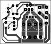

this one looks good, make a PCB yourself by toner transfer method.
hey thanks i was scared as to was it ok or good or bad or useless i m going to do a toner transfer only,,,
i m confused for should i keep the PGA2311 with 3 relay and that RCA connector on the amplifier board or just connect the thing via wire to the amp input,
- Status
- Not open for further replies.