wow! Vas parts slightly worse.
Thanks for the response. I think I found the problem.
Power dissipation 200ma
CBE 30v
Collector current 25ma (well that doesn't look great)
fT (speed) of 1.3 GHz (far off specs)
Capacitance 1pF (out of spec--did you add 4.7pf caps to them?)
HFE (gain) 25 (not enough)
Transistor suitability score F- Those probably died. Cannot diagnose amplifier until obvious causes of failures are removed. Likelihood of success is reliant on correct specs. A third try of small signal parts in the vas would be unnecessary (repeating incorrect specs will not eventually work). We're still at impasse, still awaiting correct parts. Please fix. And, good luck.
Try this website: http://alltransistors.com/transistor.php?transistor=2731 for transistor lookup (substitutions) ; however, you'll still need to verify (especially COB 4pF to 16pF) by looking in datasheets. The transistor lookup + datasheet reading prospect should work much better than random parts.
Thanks for the response. I think I found the problem.
2N5053I used 2N5053 for VAS
Power dissipation 200ma
CBE 30v
Collector current 25ma (well that doesn't look great)
fT (speed) of 1.3 GHz (far off specs)
Capacitance 1pF (out of spec--did you add 4.7pf caps to them?)
HFE (gain) 25 (not enough)
Transistor suitability score F- Those probably died. Cannot diagnose amplifier until obvious causes of failures are removed. Likelihood of success is reliant on correct specs. A third try of small signal parts in the vas would be unnecessary (repeating incorrect specs will not eventually work). We're still at impasse, still awaiting correct parts. Please fix. And, good luck.
Try this website: http://alltransistors.com/transistor.php?transistor=2731 for transistor lookup (substitutions) ; however, you'll still need to verify (especially COB 4pF to 16pF) by looking in datasheets. The transistor lookup + datasheet reading prospect should work much better than random parts.
Last edited:
2N5053
....
Transistor suitability score F-
C'mon Daniel, it's a NPN. It deserves a F(+) at least.
That's a wonderful device for a radio.C'mon Daniel, it's a NPN. It deserves a F(+) at least.
And, it is visually similar to a device that might have worked in a vas; but, that method of selecting parts would surely cost far more than buying right parts.
I'm being confused when downoading datasheets in the net the specs in the pdf file that I had for 2N5053 was so similar to that of the 2N2219 (does it mean that I got an obsolete document?) Anyway..found the suitable parts..
Attachments
Last edited:
VCEO>2*VS
2N5053, 15v C-E, handles 7+7vdc power rails
2N2219, 30v C-E, handles 15+15vdc power rails
2N2219A, 40v C-E, handles 20+20vdc power rails
PHI-BD137, 60v C-E, handles 30+30vdc power rails
2N3019, 80v C-E, handles 40+40vdc power rails
2N3499, 100v C-E, handles 50+50vdc power rails
2SC3421, 120v C-E, handles 60+60vdc power rails
However the voltage handling is not the only limiting factor since collector current and dissipation are also limiting factors.
Here's a short comparison about voltage limit:I'm being confused when downoading datasheets in the net the specs in the pdf file that I had for 2N5053 was so similar to that of the 2N2219 (does it mean that I got an obsolete document?)
2N5053, 15v C-E, handles 7+7vdc power rails
2N2219, 30v C-E, handles 15+15vdc power rails
2N2219A, 40v C-E, handles 20+20vdc power rails
PHI-BD137, 60v C-E, handles 30+30vdc power rails
2N3019, 80v C-E, handles 40+40vdc power rails
2N3499, 100v C-E, handles 50+50vdc power rails
2SC3421, 120v C-E, handles 60+60vdc power rails
However the voltage handling is not the only limiting factor since collector current and dissipation are also limiting factors.
Oscillation
Well, fire hot drivers is oscillation and if you don't have sim, scope handy, what you could do is to change vas components. The deal there is that changing the vas components unavoidably changes the vas compensation because they always work together. This could go nicely or badly. Therefore, if you put on something like the very tame 2sc3421 or the reasonably tame 2sc5171 then the vas comp is probably going to work.
Bias
After verifying correct parts and checking what you can, there's an option to hot amplifier. We could instead lower the bias. That will increase the switching which does increase the THD. Reports of how much distortion increases because of decreasing bias heat, is severely overrated and may not even be noticeable, so here's a chill out:
R14 to 51R
R8 to 1.2R
R24 to 1.8R//R11 to 1.8R (0.9R)
These four resistors are all set together if you decide to lower the bias and they can be changed if you also compare with the post 1 schematic to get the proportions (such as halfway between here and there per each resistor in the example). The above example is extreme and cuts the bias in half. That is shown for purpose of comparison.
SO, If you lower the bias but your amp is still hot, then that means the amp is oscillating.
P.S.
The CFP version is a bit touchy and if you end up with this situation, you can easily mod the CFP back to the tolerant standard version. That can help diagnosis as well.
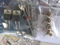
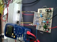
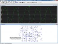
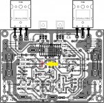
Fellows, did I measure the idle current correctly? My previous CFP build also reads 0.12ma. This is a rebuild using AlexMM pcb lay-out. All components are pretty normal excepting VAS 2N3019 they're getting hot to touch. DC-offset at 04.9mv, (no AC reading, perfect!) +/-23.7vdc rail voltage, D1047 for the output. (Sorry, not so clear images 'been using cellphone cam😀)
DC-offset at 04.9mv, (no AC reading, perfect!) +/-23.7vdc rail voltage, D1047 for the output. (Sorry, not so clear images 'been using cellphone cam😀)
An externally hosted image should be here but it was not working when we last tested it.
An externally hosted image should be here but it was not working when we last tested it.
Attachments
Last edited:
Do you mean you measured 0.12mV across the 1R resistor? This seems unlikely, with a standard multimeter the resolution is not sufficient.Fellows, did I measure the idle current correctly? My previous CFP build also reads 0.12ma.
If it's 0.12A (120mV), it is lowish but sufficient.
With 50V total supply, the 2N3019 should be reasonably hot without cooling clip, but they should remain touchable (by me anyway).
If they are really too hot, I would suspect some kind of error, pin or component swapping
Sir Elvee,
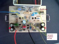
DMM set to DCmA = reads 0.12mA when set to DC = reads 47.7vdc.
Red probe to 1R and black probe to 0.47R (tap points indicated by the arrows)
I am not so sure if my manner of measuring is correct, though. PSU at -/+23vdc.
DMM set to DCmA = reads 0.12mA when set to DC = reads 47.7vdc.
Red probe to 1R and black probe to 0.47R (tap points indicated by the arrows)
I am not so sure if my manner of measuring is correct, though. PSU at -/+23vdc.
I am afraid you fried the ammeter section of your multimeter.I am not so sure if my manner of measuring is correct, though. PSU at -/+23vdc.
To measure the quiescent current, you have to connect a millivoltmeter across the 1R resistor, then Iq(mA)=VR(mV)
Uh,oh! Guess I need to check on the capabilities of my DMM, it's an auto-range type...it is supposed (programmed) to detect errors when used incorrectly. My failings' 
Thank you for correcting me.
BTW I used 2N5551 for the phase splitter.
Thank you for correcting me.
BTW I used 2N5551 for the phase splitter.
One should never use an amperemeter in an amplifier: it is dangerous both for the instrument and the amplifier.Uh,oh! Guess I need to check on the capabilities of my DMM, it's an auto-range type...it is supposed (programmed) to detect errors when used incorrectly. My failings'
Thank you for correcting me.
BTW I used 2N5551 for the phase splitter.
2N5551 are not ideal, but they should work, at least for the validation tests.
All components are pretty normal excepting VAS 2N3019 they're getting hot to touch.
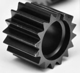
There are heatsinks made that size You can make the "flag" version at home in a couple of minutes and it would work fine with some thermal paste.
An equally important thing is airflow. In the absence of airflow the heatsink only retains heat. Therefore, be sure to allow airflow. Vents are necessary (fans are not). It is especially useful to allow the cool air in at the bottom and allow the hot air out at/near the top. That will voluntarily make a silent breeze and enough circulation to make the heatsink work.
Attachments
Last edited:
Another candidate
Has the FCX458 been evaluated for use as VAS?
*
.MODEL FCX458 NPN IS=5.32E-14 NF=1 BF=230 IKF=1.5 VAF=1500
+ ISE=2.1E-14 NE=1.385 NR=1.05 BR=8 IKR=0.7 VAR=64 ISC=6.42E-12
+ NC=1.25 RB=0.5 RE=0.224 RC=0.134 QUASIMOD=1 RCO=80 GAMMA=4E-7
+ CJC=9.5E-12 MJC=0.32 VJC=0.4 CJE=115E-12 MJE=0.37 VJE=0.8
+ TF=1.3E-9 TR=16E-6 TRC1=.004 TRB1=.004 TRE1=.004 XTB=1.4
*
*$
It is widely avalable and cheap.Ok is SMT but it can make the design much more robust against higer rail voltages.
400V and a Hfe of >100 output capacity 5pF
It works transparently in sim, and it is highly likely it also would in reality.
Two things concern me though:
-The Ft is rather lowish: 50MHz (OK, it's the min value)
-Such high voltage transistors tend to have a relatively large knee voltage; this might affect the negative swing.
You should try them, keeping the above points in mind (and report the results, it will be useful to other members)
Attachments
Has the FCX458 been evaluated for use as VAS?
As far as I know, high voltage voltage transistors meant to be used at high voltages relatively. Additionally, datasheet says fT is 50mhz, which is not desirable value for VAS. There are some far better choices in SMD form as Daniel noticed earlier.
Elvee? What is the minimum collector current tolerance for VAS (Q5, Q6) transistors?
What operating voltage (rails, power) do you suggest as maximum when using these FCX458 devices.
P.S.
I believe that the transistor speed only has to meet the demand of the amplifier. And the Circlophone, while not winning any speed races with the output devices, has both wide tolerances and no slow sections, so overall acts quite fast enough. Even so, if slower devices are used in the VAS, I believe that one would want to keep the gain normal/lowish as shown in the original Circlophone schematic. Right?
I mean, that if the VAS parts are 50mhz, we wouldn't want to crank the gain up to 48--is that basically correct? If I knew where we maxed for gain (prior to "revealing" the slow vas) if given a 50mhz vas, then it would be a really easy job to use permissible gain for estimate operating voltage range, since a bigger power amp transformer doesn't make the source bigger at all. For the big picture, I wonder where the operating voltage and gain specs will all match up, but like some of the other SMD VAS, I expect a nice "desktop amp" size/scale amplifier, and in that case the good news is that the specs will probably all line up reasonably.
EDIT: Simplified version of same question: The voltage is not a limiting factor on FCX458 for VAS, but how about the speed and the current/heat tolerances?
Last edited:
Elvee? What is the minimum collector current tolerance for VAS (Q5, Q6) transistors?
What operating voltage (rails, power) do you suggest as maximum when using these FCX458 devices.
Dimensionning of the VAS has been explained at length in the main thread.
Basically there are no issues regarding current, and they could theoretically be used at up to +/-70V
Speed could be a problem if other devices are also marginalEDIT: Simplified version of same question: The voltage is not a limiting factor on FCX458 for VAS, but how about the speed and the current/heat tolerances?
Soon I will be building another Circlophone. This time I want to try the BC560C/BC550C integral buffer mod for the input (for compatibility with my blarebuster passive preamp plus clipnipper limiter) and also considering the addition of the offset trimmer.
Got the BD911's or MJE3055's standing by for test, and will replace with MJL21194's after successful start up.
Got the BD911's or MJE3055's standing by for test, and will replace with MJL21194's after successful start up.
- Home
- Amplifiers
- Solid State
- Building Elvee's Circlophone: Documentation, Parts, Accessories, & beginner friendly