Hello
I have a Sansui 221 with blown STK013 power amp chip. As far as I know, the Chinese replacements are crap.
So I'd like to try to build a direct replacement for this stereo amplifier chip.
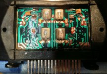
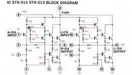
In the Sansui Service Manual there's a schematic of the chip, but without any values. I opened it up und measured the resisitors.
I already simulated the circuit with LTSpice and it seems to work.
As I don't fully understand the circuit, I have a few questions:
- What transistors need to be thermically coupled to the power transistors?
- Are the resistor values about right?
My next step would be to build the circuit on a breadboard and see if it works.
Regards
Christian
I have a Sansui 221 with blown STK013 power amp chip. As far as I know, the Chinese replacements are crap.
So I'd like to try to build a direct replacement for this stereo amplifier chip.
In the Sansui Service Manual there's a schematic of the chip, but without any values. I opened it up und measured the resisitors.
I already simulated the circuit with LTSpice and it seems to work.
As I don't fully understand the circuit, I have a few questions:
- What transistors need to be thermically coupled to the power transistors?
- Are the resistor values about right?
My next step would be to build the circuit on a breadboard and see if it works.
Regards
Christian
Attachments
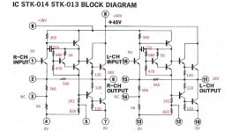
So this is an almost complete power amp - singleton input, VAS, quasicomp output stage. All that has to be added externally is a feedback R/C for the desired gain at pin 2 (here 150R/220µ) and a bootstrap capacitor between 6 and 5.
TBH, if I had to build a replacement in this day and age, I would consider going with a more modern circuit to begin with. In the early 1970s, a singleton input and quasicomp output stage were almost a given, but nowadays you might just as well implement a regular complementary output stage, and there is nothing really keeping you from implementing an LTP input either, just as long as the feedback resistor stays a 5k6 (the other 5k6 down to pin 3 and the 56R to pin 4 - I'm assuming for RC filtering when using a split supply - would have to be resized for good LTP symmetry). Nobody uses a Darlington for the bias spreader any more either, not sure why they did that to begin with.
What I'd consider problematic is the lack of any output transistor emitter resistors - perhaps the silicon they used effectively included some (à la hometaxial 2N3055), or thermal coupling to the bias spreader transistors was good enough that they had good thermal tracking anyway.
Is size a major concern or does it mainly have to be pin-compatible?
1)What do you mean by
2) in any case you will NOT be able to home build a clone which fits in the same size space, and you do NOT have the needed power transistor raw chips, and even if you did, no way to mount them on a thermally useful backplate.
You may build a discrete version, using prepackaged transistors, but it will be 2 to 4 times larger so will not fit the current amp.
3) given this, I would trust the Chinese replacements, if anything because they are Industrially made and they have the machinery and resources to build thick film hybrid modules ... which can NOT be kludged at home, definitely in such a compact package.
😕the Chinese replacements are crap
2) in any case you will NOT be able to home build a clone which fits in the same size space, and you do NOT have the needed power transistor raw chips, and even if you did, no way to mount them on a thermally useful backplate.
You may build a discrete version, using prepackaged transistors, but it will be 2 to 4 times larger so will not fit the current amp.
3) given this, I would trust the Chinese replacements, if anything because they are Industrially made and they have the machinery and resources to build thick film hybrid modules ... which can NOT be kludged at home, definitely in such a compact package.
Said Chinese replacements (counterfeits) generally seem to be using off-the-shelf SMD components from what I've seen, so no bare die transistors either. It's hardly a surprise they're not as robust as the originals.
With some vertical integration, you may be able to engineer a replacement. Two pairs of Sanken complementary darlingtons, bias spreaders, and emitter resistors all mounted on a small board might just fit in the same area as the original STK. put all the small signal components on another daughter board that mounts above the power board with a set of header pins down each side. No SMDs needed, although if you can work with them all the small signal stuff might just fit with the darlingtons. The whole assembly can be mounted directly to the same heat sink the STK was, using the power transistor packages as mounting points. You’ll have to drill 6 new holes in the heat sink (use self tapping #4’s).
FYI, I made a STK-0050 replacement for the DIY community. Initially it was for a Pioneer SX-780, but others have been using them in other gear.
STK-0050 replacement for SX-780 and others | Audiokarma Home Audio Stereo Discussion Forums
It did require that a Al plate be fabricated. There are mechanical details that need to be figured out for these designs to fit the intended application, as making some thing exactly the same as original is not going to fly since we are not going to design a new hybrid module for DIY.
Attachments
My goal is to build a pin compatible 1:1 replacement which should be installable at the same spot in the amplifier, maybe with drilling some additional holes. I'd like to use discrete components. I'm quite sure that it is possible to build this, maybe with SMD resistors if space is a problem.
The chinese replacements are often SMD components and tend to fail.
After further investigation of the broken module, I saw, that the darlington is actually just a single transistor. So i corrected the schematic and my simulation. In the simulation the cuircuit works.
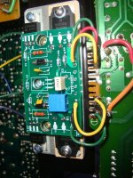
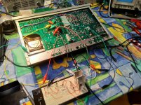
Yesterday I built the circuit on a breadboard an connected it to the amplifier. I added 0.47 Ohm Emitter resistors. It oscillated at 200kHz, but that is probably because of the long wires everywhere. Putting a bigger capacitor of about 200pF in, cured it for output levels of max 1V peak. However bigger signals started oscillation again.
Which transistors need to be on the same heatsink? The bias spreader and the power transistors? The drivers too?
The chinese replacements are often SMD components and tend to fail.
After further investigation of the broken module, I saw, that the darlington is actually just a single transistor. So i corrected the schematic and my simulation. In the simulation the cuircuit works.
Yesterday I built the circuit on a breadboard an connected it to the amplifier. I added 0.47 Ohm Emitter resistors. It oscillated at 200kHz, but that is probably because of the long wires everywhere. Putting a bigger capacitor of about 200pF in, cured it for output levels of max 1V peak. However bigger signals started oscillation again.
Which transistors need to be on the same heatsink? The bias spreader and the power transistors? The drivers too?
Attachments
Hardly a surprise - the original chip uses a compact, low-inductance layout. Yours would need some local rail decoupling at the very least. Also twist the B+ / power ground leads.Yesterday I built the circuit on a breadboard an connected it to the amplifier. I added 0.47 Ohm Emitter resistors. It oscillated at 200kHz, but that is probably because of the long wires everywhere. Putting a bigger capacitor of about 200pF in, cured it for output levels of max 1V peak. However bigger signals started oscillation again.
Besides, did you check bias levels? You have different transistor types in now (could you give a quick rundown of what you used?) with potentially higher emitter resistance than the original - if the outputs are severely underbiased and possibly slow to begin with, a tendency towards oscillation would not be a surprise. Measure voltage drop across one emitter resistor while nothing is oscillating, it should be maybe 10-15 mV. If the bias transistor is not a Darlington, I would expect a bias voltage of maybe 1.6 V with stock resistor values, leaving maybe 0.2 V each for the outputs, which is not enough by far. You may be getting close with ca. 1k2 instead of 680R; I'd try 1k - 1k1 - 1k2 - 1k3 - 1k4, combining resistors as needed.
Yes.Which transistors need to be on the same heatsink? The bias spreader and the power transistors? The drivers too?
A low-power amp like this does not strictly need its drivers on the heatsink if they can dissipate enough on their own (and a TO-92 will in fact do), but it does improve thermal stability a fair bit.
This sort of thing would be a good use for the Sanken STD power darlingtons with builtin thermal diodes
edit: never mind, it's a quasi complimentary output. Some TO-220 darlingtons would work well enough though as the driver+outputs, and SMD parts for the rest.
edit: never mind, it's a quasi complimentary output. Some TO-220 darlingtons would work well enough though as the driver+outputs, and SMD parts for the rest.
Last edited:
I used 2SC945 for the small power NPN, 2SA1015 for the small signal PNP and 2N6488 for the power transistors. If you look at the last schematic I posted, i already replaced the 680R with 1.2K, that's what I use at the moment.
I just increased the value to 1.4K, this stopped oscillation and the output work now up to almost +-20V.
My voltage divider at the bias spreader is now 1.4k and 470R. Bias at the lower trans is 25mV, at the upper trans 80mV. Why is this so different? How can I correct it?
I measure the lower base of the driver trans at 18.4V, the upper base of the driver at 21.4V.
Why not drop in a chip amp, e.g. LM3886 or TDA7294 or something like that, plus an adaptor board?
Best regards!
Best regards!
Why not drop in a chip amp, e.g. LM3886 or TDA7294 or something like that, plus an adaptor board?
Best regards!
Well, I already tried using a LM3886 and removing all the surrounding parts of the old chip. It worked, but I had 2 Problems:
- There was a 100Hz hum at the output which looked like ripple of the power supply. I never found a way to cure this.
- There was a very loud plopp at the speakers at switching on the amplifier. I also found no easy way to solve this.
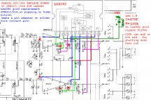
stk013 / 014 good replacement LA4282 single power supply.
no popping , no humm
see pic .
also can change c33,c34 to 0.047uf more sound bandwidth
no popping , no humm
see pic .
also can change c33,c34 to 0.047uf more sound bandwidth
Hello
I have a Sansui 221 with blown STK013 power amp chip. As far as I know, the Chinese replacements are crap.
So I'd like to try to build a direct replacement for this stereo amplifier chip.
In the Sansui Service Manual there's a schematic of the chip, but without any values. I opened it up und measured the resisitors.
I already simulated the circuit with LTSpice and it seems to work.
As I don't fully understand the circuit, I have a few questions:
- What transistors need to be thermically coupled to the power transistors?
- Are the resistor values about right?
My next step would be to build the circuit on a breadboard and see if it works.
Regards
Christian
Attachments

stk013 / 014 good replacement LA4282 single power supply.
no popping , no humm
see pic .
also can change c33,c34 to 0.047uf more sound bandwidth
last change pic
Attachments

This sort of thing would be a good use for the Sanken STD power darlingtons with builtin thermal diodes
edit: never mind, it's a quasi complimentary output. Some TO-220 darlingtons would work well enough though as the driver+outputs, and SMD parts for the rest.
All SMT devices on an IMS (aluminium core) pcb is a possibility.
stk013 / 014 good replacement LA4282 single power supply.
no popping , no humm
see pic .
also can change c33,c34 to 0.047uf more sound bandwidth
last change schematic update
joy
Attachments
This sort of thing would be a good use for the Sanken STD power darlingtons with builtin thermal diodes
edit: never mind, it's a quasi complimentary output. Some TO-220 darlingtons would work well enough though as the driver+outputs, and SMD parts for the rest.
It would take virtually no effort to convert it to fully comp and then use the STD Darlingtons.
Looks easy.
- Home
- Amplifiers
- Solid State
- Building a STK013 / STK014 replacement