I like challenges … so I decided to give it a try.
Part One of many:
Credits go to: BUG AMPS , bugamps.com, A Big Thank You for the support I received so far!!!
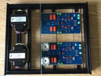
The concept, a schematic tells it all…

The PSU, another nice schematic…

To be continued with Part Two: Some knowledge.
Part One of many:
Credits go to: BUG AMPS
, bugamps.com, A Big Thank You for the support I received so far!!!The concept, a schematic tells it all…
The PSU, another nice schematic…
To be continued with Part Two: Some knowledge.
Part Two: Some knowledge
Among my favorite reads:


Basic knowledge about tubes:

https://m.youtube.com/results?sp=mAEA&search_query=Bug+amps+load+curves A bit lengthy, but not long enough for me, had to watch it twice to get it, lol
To be continued with Part Three: Understanding the design
Among my favorite reads:
Basic knowledge about tubes:
https://m.youtube.com/results?sp=mAEA&search_query=Bug+amps+load+curves A bit lengthy, but not long enough for me, had to watch it twice to get it, lol
To be continued with Part Three: Understanding the design
Part Three: Understanding the design (through simulation)
This is my personal approach as it helps me to understand what’s going on in a design without smoke, tears and regrets…
Credits go to several folks in this forum for the spice models I ‘borrowed’ from here!
The PSU:

The GSU:

The DCFil ( my option with LT1764, Bug Amp use DC : DC converter and a LD1084. In my final setup I’ll test both designs with a DC : DC converter as it reduces load onto the regulators (see original Bug Amp PSU schematic).
The Amp:

PS.
I can share the LTSpice models if interest exist. Bit complicated since my stupid way of organizing libraries I have to collect the special parts individually. I apologize for the mess, but I learned LTSpice on the fly and on a Mac I made some quick and dirty fits…
To be continued by Part Four: Components
This is my personal approach as it helps me to understand what’s going on in a design without smoke, tears and regrets…
Credits go to several folks in this forum for the spice models I ‘borrowed’ from here!
The PSU:
The GSU:
The DCFil ( my option with LT1764, Bug Amp use DC : DC converter and a LD1084. In my final setup I’ll test both designs with a DC : DC converter as it reduces load onto the regulators (see original Bug Amp PSU schematic).
The Amp:
PS.
I can share the LTSpice models if interest exist. Bit complicated since my stupid way of organizing libraries I have to collect the special parts individually. I apologize for the mess, but I learned LTSpice on the fly and on a Mac I made some quick and dirty fits…
To be continued by Part Four: Components
Attachments
Part Four: Components
to be continued with Part Five: KiCad design (schematics and PCB)
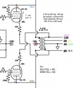
- Mains Transformer, Antek 2T230 and 1T275
- OT, Hammond 1650NA, through Mouser
- chokes 157G, through Mouser
- see Mouser BOM
- DC DC XL4015, Amazon
- other parts Mouser, see BOM
- Tubes, 6N23P, 6E5P - Amazon, GU-50 incl. Sockets from Sovtube, Ukraine, via eBay.
- Softstart: re-build based on Antek SS12 (
https://www.antekinc.com/)
- PCBs: JLCB China
- case, my personal nightmare, not yet decide, probably extruded 2020 frame with aluminium cladding , will see
to be continued with Part Five: KiCad design (schematics and PCB)
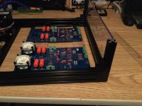
Attachments
Part Five: KiCad design
This is my re-build design. It contains
Again I apologize for the library mess you might need additional parts I designed, like the GU-50 sockets.
Post what’s missing and I’ll collect it, based on interest.
To be continued with Part Six: The build
This is my re-build design. It contains
- Softstart module based on Antek
- DCFil (two options), Bug Amps and my own LT1764 design (I pre-used on a Ear Phono Amp)
- PSU
- GSU
- PP AMP, I made two designs, normal with only the tubes on bottom side and one with everything flipped depends what setup you prefer (which side of the PCB you want the tubes on)
Again I apologize for the library mess you might need additional parts I designed, like the GU-50 sockets.
Post what’s missing and I’ll collect it, based on interest.
To be continued with Part Six: The build
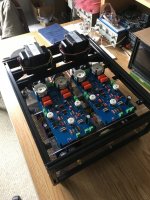
Attachments
Part Six: The Build
Buy the Softstart from Antek, I forgot and because of exorbitant shipping cost I decided to re-build them from scratch. Not worth it.
… waiting on the PCBs from China. I might have a few surplus as I have to order in batches of 5. I will sell a batch for $50. This includes the Softstart, PSU, GSU, 2X DCFil (both options), 2X amp (flipped and non-flipped, they’re identical apart from the component Silk Screen, so, if you have both options it’s easy to distinguish)
First thing todo when I receive the tubes, is to run them through my Elektor TubeTracer (are excellent design by R.Schuster from the Elektor team, they have a homepage with the whole project on, I can help if you decide to re-build this excellent tool) and record/compare there load curves. Than fill the PCB boards, DCFil, PSU, GSU, then use a Variac to check voltages and check for smoke, lol. Then go for the amps. And finally build a case, my nightmare…
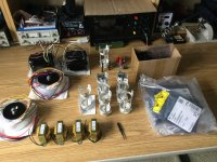
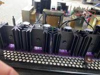
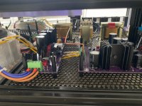
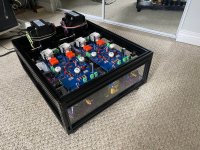
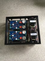
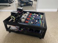
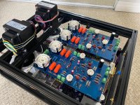
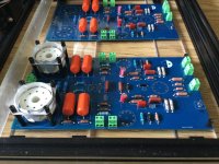
Parts received:
If you look careful, you’ll see GU-50 tube test prepared (it’s a bit dirty, IK, but saves the day). I’ll do a strapped test, triode mode, screen voltage follows anode to see how the tube behaves.
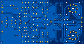
PCB design, flipped shown:
About me:
I build my first tube amp 50 years ago, from salvaged WWII and RFT radios. I have no expert knowledge in electronics. I am an inactive radio amateur and recently retired to finally find time to burn down the house, lol
But, IK what are does and donuts and howto get rid of humus…
Constructive criticism is welcome, let’s make this a great project. And again thanks to BUG AMP and the folks here for models.
Buy the Softstart from Antek, I forgot and because of exorbitant shipping cost I decided to re-build them from scratch. Not worth it.
… waiting on the PCBs from China. I might have a few surplus as I have to order in batches of 5. I will sell a batch for $50. This includes the Softstart, PSU, GSU, 2X DCFil (both options), 2X amp (flipped and non-flipped, they’re identical apart from the component Silk Screen, so, if you have both options it’s easy to distinguish)
First thing todo when I receive the tubes, is to run them through my Elektor TubeTracer (are excellent design by R.Schuster from the Elektor team, they have a homepage with the whole project on, I can help if you decide to re-build this excellent tool) and record/compare there load curves. Than fill the PCB boards, DCFil, PSU, GSU, then use a Variac to check voltages and check for smoke, lol. Then go for the amps. And finally build a case, my nightmare…
Parts received:
If you look careful, you’ll see GU-50 tube test prepared (it’s a bit dirty, IK, but saves the day). I’ll do a strapped test, triode mode, screen voltage follows anode to see how the tube behaves.
PCB design, flipped shown:
About me:
I build my first tube amp 50 years ago, from salvaged WWII and RFT radios. I have no expert knowledge in electronics. I am an inactive radio amateur and recently retired to finally find time to burn down the house, lol
But, IK what are does and donuts and howto get rid of humus…
Constructive criticism is welcome, let’s make this a great project. And again thanks to BUG AMP and the folks here for models.
Attachments


I got the first batch of tubes, 6E5P. Word of advice: Do not buy second hand tubes from Amazon!
TG was only $20…
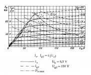
 Tube curve tracer in action, Tetrode 6E5P in triode mode and the crap revealed

Number one is complete garbage (tube has an issue of G1 and G2 ‘isolation’ as soon as Vg2 reaches a certain value (~130V) Vg1 jumps in hoops, it changes magically). Anyone can explain to me what could be wrong with that tube, just out of curiosity). Three won’t match two and for. Two and four probably ok as a pair to drive GU-50 end stage.
I ordered brand new ones now a few more to be able to better match them. For the 6N23P I ordered a pair of matched.
TG was only $20…
Tube curve tracer in action, Tetrode 6E5P in triode mode and the crap revealed
Number one is complete garbage (tube has an issue of G1 and G2 ‘isolation’ as soon as Vg2 reaches a certain value (~130V) Vg1 jumps in hoops, it changes magically). Anyone can explain to me what could be wrong with that tube, just out of curiosity). Three won’t match two and for. Two and four probably ok as a pair to drive GU-50 end stage.
I ordered brand new ones now a few more to be able to better match them. For the 6N23P I ordered a pair of matched.
If you’re seeing weird behavior, it may be the tube is going into some high frequency oscillation? I’ve heard of that happening on tube testers before. Hickok added ferrite beads of some sort right at the socket pins to deal with this. Some of the tubes we use for audio are made for uhf radio work, and are quite capable of sustained oscillation at frequencies you wouldn’t think to look at.
or maybe the tube is just bad.
or maybe the tube is just bad.
I think I heard this one tube ringing before I cut power. What kind of ferrite bead is required?
The other tubes behaved ok, with number three a bit behind on Ia. I am on my way to build a proper switch board with tube sockets of different kind to be able to test other types without soldering. So, a recommendation of ferrite beads would be welcome…
The other tubes behaved ok, with number three a bit behind on Ia. I am on my way to build a proper switch board with tube sockets of different kind to be able to test other types without soldering. So, a recommendation of ferrite beads would be welcome…
There are so many variables, and I have so little understandingI think I heard this one tube ringing before I cut power. What kind of ferrite bead is required?
The other tubes behaved ok, with number three a bit behind on Ia. I am on my way to build a proper switch board with tube sockets of different kind to be able to test other types without soldering. So, a recommendation of ferrite beads would be welcome…
") hopefully someone wiser can help you with that. They're not very big, and basically turn the wire into a better inductor at RF frequencies, without causing issues at audio frequencies.
hopefully someone wiser can help you with that. They're not very big, and basically turn the wire into a better inductor at RF frequencies, without causing issues at audio frequencies.It’s ready!
Final Gerber files attached.
Last but not least a Big Thank You to Bug Amps. This is a wonderful design. Even with these rel. cheap Russian tubes this is a tube amp worth building!!!
Final Gerber files attached.
Last but not least a Big Thank You to Bug Amps. This is a wonderful design. Even with these rel. cheap Russian tubes this is a tube amp worth building!!!
Attachments
-
 B923EEF2-E5B4-4E90-81F8-FDAB294355DC.jpeg512.6 KB · Views: 300
 -
 9CB9CC48-CB21-440D-ACC2-201BCF11C95E.jpeg751.3 KB · Views: 277
 -
 22324467-3761-4893-8780-CB05FC47D1BB.jpeg511 KB · Views: 236
 -
 B8E878E0-656C-4DD8-BB1A-1625BF489F0D.jpeg504.1 KB · Views: 243
 -
 79EBC983-8204-4532-A610-F580DE686667.jpeg796.7 KB · Views: 243
 -
 B4AD7A02-C8C8-437C-A79E-C54F85DD2E01.jpeg717 KB · Views: 244
 -
 C702CB71-F475-4D71-8728-C05F59EBA010.jpeg897.9 KB · Views: 236
 -
 0B492091-A38A-4D89-9C2C-670AAFE7BC74.jpeg725.7 KB · Views: 220
 -
 30FE743E-4E32-4816-B5F6-66F0656A77D7.jpeg689 KB · Views: 214
 -
 6773DC3F-E25A-4823-8237-4D5E5FEC69AA.jpeg721 KB · Views: 210
 -
 C7C516FC-A2C4-493C-A37A-CFBC6E7E1FD3.jpeg554 KB · Views: 297
 -
 2E5D8038-33FF-42D9-8106-018B7002ED8D.jpeg182 KB · Views: 304
 -
 E7FEF3B3-1732-491F-A8EA-28A85B6A4F8B.jpeg488 KB · Views: 285
 -
 15F6B900-3E43-4C85-92F8-130AD1372214.jpeg528.3 KB · Views: 177
 -
 BC7A8997-5C22-46E0-A3D7-EB82DF851B4F.jpeg523.7 KB · Views: 207
 -
 1B53A0E5-A6F2-426F-8E32-16649EE368DE.jpeg512.6 KB · Views: 289
 -
PP.zip1.3 MB · Views: 139
Last edited:
That looks very good, nice work, well done. Re parasitic oscillation I've found ferrite beads to be ineffective as they only seem to work at a frequency higher than the oscillation, all the oscillation I've come across has been under 200khz, most well under that. Also to be really effective you have to fit the bead on or as near tothe valve base bin which can be very tricky. not to say that it won't work in your case, as in any issue it helps if you know what frequency you're dealing with.
A better fix is an anode resistor, something like 100r and a bigger grid stopper. I always fit HPF's, a zobel network & configure the NFB RC to roll off response over 45khz ish, and or a LF shelving to my bigger amps so that they're rock solid with any speaker.
If it's just one valve try swapping it with another to see if it's a layout issue, if it is moving ground's might help as well as better HT/B+ de-coupling as well as a 1u & 0.1u in parallel with your PSU reservoir/smoothing caps.
Again, you've built a grand amplifier there, happy listening, Andy.
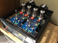
I’ll be doing that, measure THD and impedance. I have the Soundcard IF and a non inductive load (similar to the one attached, from the building tube amps book) ready but no super duper SC just a 96kHz Focusrite Saffire. I guess it’ll be enough for this purpose. So far its running rock solid (I had it rocking yesterday for 3 hours and I never experienced Everlast’s “Eat At Whitney’s” with such a nice bass!!!). I got spousal approval!Nice. I see cathode feedback and Schade feedback, but no global feedback. Did you measure the output impedance and THD? A moderate GNFB doesn't hurt, I learned it from my experience.
No oscillation, absolutely no noise on right channel (really dead silent, w/o source, yeah!) and a tiny little noise on the left (I can hear in the high efficient Quadral Amun Speakers connected when I put my ear on the box, nothing in 1m distance). I have to root this out. I suspect the input RCA or one cable (my cable management is terrible
) or the input tube or one driver, or…I consider myself an amateur. I build stuff and know something, but far less then a pro. Based on that one can say this build is rel. easy to build. The design is rock solid and no tricky adjustments required apart from being careful wiring the driver heating (6.3AC), driver BIAS and OT. Matching tubes is a must and will avoid all kind of hassle. My simulation helped a lot to understand what’s going on.
P.S. The oscillation I reported earlier was on the Tube Curve Tracer and actually was the cheap Chinese 9P socket I hand wired carelessly. I got it fixed and was able to pair ALL tubes nearly perfectly. All tubes tested in triode mode, since I destroyed one 6E5P trying to test in Tetrode mode (150V on g2 with a=0 made g2 become an Anode, remember my post where I asked exactly this question, ok, learning by doing. I am still curious how the tube manufacturers measure their curves, see picture attached).
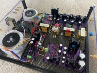
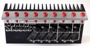
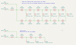
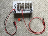
Another tool what helped a lot to nail the PSU and streamline heat sink arrangement was a lamp tester I build myself. It’s a series of lamps 120V/15W E12, 12x and 120V/3W which can be easily arranged in series or parallel and enable the test under load. Quick and dirty but very effective. The amp PSU is slowly ramping up, so the cold resistance of the lamp filaments is no issue and it’s nice to see the lamps going from glow to full brightness. With six in series you can test upto 720V/120mA or parallel 240mA. The 3W bulbs are ~25mA at 120V.
Attachments
Found it!
Entry stage DC6.3 heater wiring, just re-routed and installed a 100R antenna. I wrapped a wire around the DC6.3 hot wire and took this via 100R to GND, done. I have a GND bus so the hot wires go single wire to the supply terminals. So, that one heater wire caught electrostatic hum from the air. The other one is fine. I love tube amps!
Entry stage DC6.3 heater wiring, just re-routed and installed a 100R antenna. I wrapped a wire around the DC6.3 hot wire and took this via 100R to GND, done. I have a GND bus so the hot wires go single wire to the supply terminals. So, that one heater wire caught electrostatic hum from the air. The other one is fine. I love tube amps!
- Home
- Amplifiers
- Tubes / Valves
- Building a PP - BugAMP design with GU-50