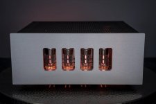
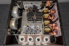
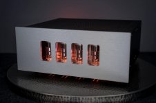
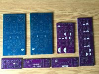
I'm the "other guy" from BugAmps. Sean, not Doug. First, let me say, kudos on the implementation to tubekiddo. This is not a simple amp to build. I really like the layered chassis, It's beautiful.
This amp design was all Doug, but I'll try to give a few answers. Doug is free to jump in and correct anything I say. We've used GNFB in some designs, but its not always necessary. GNFB requires extra gain to throw away and that tends to worsen SNR and distortion before you try to fix it, and IMO, it tends not to fix the noise issue beyond getting you back to where you'd be with lower gain and no GNFB. With good transformers you can get acceptable FR as well. The 2 biggest advantages for GNFB is that is minimizes variance based on tube mismatching and makes flat FR easier with moderately priced transformers. It is therefore critical for mass market amps where 1) savings on TX's = profit and 2) the end user is unlikely to have the ability to carefully measure and match tubes. As a hobbyist, these are not significant concerns.
Here Doug was able to get a tolerable FR, distortion, noise, and output impedance without it. Doug used an old pair of A470 as output transformers, so tubekiddo's amp may measure a bit different.
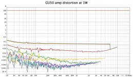
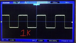
Doug and I tend to like moderate output impedance amps, 2-5R on the 8R tap, half that on the 4R tap. Doug's version was right around 4R on the 8R tap. We also tend to value first-watt performance and progressive distortion over a typical GNFB amp that has a hard distortion cliff near clipping. Breadboard measurements with random tubes are the only ones I have at hand, so they likely will be slightly better with better matched tubes. FR was down less than 0.5db at 20K and just about 1.5dB at 20hz. I don't think the measurements have a loopback correction applied, so its probably significantly better than that in actuality. Squarewave shows zero overshoot, so the ultra HF are well behaved.
1K/1W performance is circa 0.3%. That was predominantly 2nd order, 3rd order was circa 0.1%. With good matching .15% is easily achievable. Measured at 1%, you probably only are getting about 10W from the amp, but distortion remains low order (2nd and 3rd dominant) and is progressive. 3% should happen mid 20W, and the amp doesn't hard clip until past 36W. Unlike a GNFB amp, the distortion is reasonably consistent over all frequencies, with no rise at HF and only rising below about 35hz.
Could a different front end be put in there with more gain and 10-15 dB of feedback be looped around this amp? Sure, especially with the well behaved A470. Would it have lower THD between 5W and 30W? Again, sure. But only at the frequencies where the FB was effective and only in the lower order distortion. Would it sound better? From my experience, I doubt it. I actually haven't yet heard this amp; but I've heard, optimized, and measured a bunch of amps we've built and its pretty clear which ones I like. I'd bet money that this is one of them. I've attached a few pics of Doug's implementation and some measurements below.
This amp design was all Doug, but I'll try to give a few answers. Doug is free to jump in and correct anything I say. We've used GNFB in some designs, but its not always necessary. GNFB requires extra gain to throw away and that tends to worsen SNR and distortion before you try to fix it, and IMO, it tends not to fix the noise issue beyond getting you back to where you'd be with lower gain and no GNFB. With good transformers you can get acceptable FR as well. The 2 biggest advantages for GNFB is that is minimizes variance based on tube mismatching and makes flat FR easier with moderately priced transformers. It is therefore critical for mass market amps where 1) savings on TX's = profit and 2) the end user is unlikely to have the ability to carefully measure and match tubes. As a hobbyist, these are not significant concerns.
Here Doug was able to get a tolerable FR, distortion, noise, and output impedance without it. Doug used an old pair of A470 as output transformers, so tubekiddo's amp may measure a bit different.
Doug and I tend to like moderate output impedance amps, 2-5R on the 8R tap, half that on the 4R tap. Doug's version was right around 4R on the 8R tap. We also tend to value first-watt performance and progressive distortion over a typical GNFB amp that has a hard distortion cliff near clipping. Breadboard measurements with random tubes are the only ones I have at hand, so they likely will be slightly better with better matched tubes. FR was down less than 0.5db at 20K and just about 1.5dB at 20hz. I don't think the measurements have a loopback correction applied, so its probably significantly better than that in actuality. Squarewave shows zero overshoot, so the ultra HF are well behaved.
1K/1W performance is circa 0.3%. That was predominantly 2nd order, 3rd order was circa 0.1%. With good matching .15% is easily achievable. Measured at 1%, you probably only are getting about 10W from the amp, but distortion remains low order (2nd and 3rd dominant) and is progressive. 3% should happen mid 20W, and the amp doesn't hard clip until past 36W. Unlike a GNFB amp, the distortion is reasonably consistent over all frequencies, with no rise at HF and only rising below about 35hz.
Could a different front end be put in there with more gain and 10-15 dB of feedback be looped around this amp? Sure, especially with the well behaved A470. Would it have lower THD between 5W and 30W? Again, sure. But only at the frequencies where the FB was effective and only in the lower order distortion. Would it sound better? From my experience, I doubt it. I actually haven't yet heard this amp; but I've heard, optimized, and measured a bunch of amps we've built and its pretty clear which ones I like. I'd bet money that this is one of them. I've attached a few pics of Doug's implementation and some measurements below.
Attachments
-
 286367441_344216311184811_4600497486133990746_n.jpg136.8 KB · Views: 247
 -
 286308732_539758334360611_5282947711361937311_n.jpg313.5 KB · Views: 242
 -
 285078959_534718668134810_5306974318928319033_n.jpg133.7 KB · Views: 238
 -
 Distortion 1W.jpg116.4 KB · Views: 187
 -
 Distortion 18W.jpg107.1 KB · Views: 197
 -
 162026909_220269706552196_5567966723270106240_n.jpg50.2 KB · Views: 208
Last edited:

Just in case somebody is interested. I have a bunch of PCBs left over. The full set is 6 (Softstart, PSU, GSU, DCFil or DCFilAlternative, 2X amp (mirror tube arrangement or non-mirrored, PCB top or bottom). I am selling the full set for $50 + shipment (set is ~500g, just over a lbs).
A few minor issues to consider (since it is v0.9). Version 1.0 attached Gerber files don’t have these issues!
On PSU and GSU board the mosfets have the wrong package DGS instead of actual GDS, so you need to swap D and G (bend pins and solder a short extension to G, no big deal.
On amp board the LM334 has tight spacing. Need a small solder iron tip to not short them out.
None of my boards follow diyAudio mounting hole spacing specifications 🙁.
Don’t use the heater terminal on the GSU board, hum will be introduced. Instead air wire the AC6.3 (see my final pics).
Softstart. Wire a 47D-15 to bridge the 10R load resistors and bend it down onto the resistors. Will give you a nice 3-5s start delay on power up and suppress every power surge effectively.
Attachments
To second one aspect of what Sean’s said above. I’ve never heard a better amp before. I am sure there are better ones, but I’ve not had the opportunity to listen to one. I have a BalladAudio Melody SP3 with 4x 6E13 (~20W) and this is absolutely NO match…
I have a Tube Curve Tracer, see one of my posts here, which I used to pair driver and end stage tubes! I used Hammond 1650NA OTs from Mouser and Antec power transformers.
I have a Tube Curve Tracer, see one of my posts here, which I used to pair driver and end stage tubes! I used Hammond 1650NA OTs from Mouser and Antec power transformers.
Last edited:
You can actually and it works super, smoothing out the -100V.
I have attached a LTSpice model at the beginning of this thread.
I have attached a LTSpice model at the beginning of this thread.
THD, with my rebuild I achieve about the same as seanzozo reported above.
I can send you a set of PCBs for shipping cost only, BUT these are first generation with some errors. I screwed up all Mosfet packages pinouts on the PSU boards and on the amp board the constant current IC has to tight spaces. All theses issues have been corrected in version 2 which are attached in my post. So, I’d not recommend my left overs.
1K/1W performance is circa 0.3%. That was predominantly 2nd order, 3rd order was circa 0.1%. With good matching .15% is easily achievable. Measured at 1%, you probably only are getting about 10W from the amp, but distortion remains low order (2nd and 3rd dominant) and is progressive. 3% should happen mid 20W, and the amp doesn't hard clip until past 36W. Unlike a GNFB amp, the distortion is reasonably consistent over all frequencies, with no rise at HF and only rising below about 35hz.
I can send you a set of PCBs for shipping cost only, BUT these are first generation with some errors. I screwed up all Mosfet packages pinouts on the PSU boards and on the amp board the constant current IC has to tight spaces. All theses issues have been corrected in version 2 which are attached in my post. So, I’d not recommend my left overs.
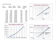
Looks like one type of lamp you are using is the 3S6, Here are some test results you might find useful.
This is the kind of lamp used in analogue audio oscillators such as the HP 200CD. It can be used in Bridged=T oscillators as well.
The application of a tungsten lamp in a FB netwok was Bill Hewlett's (HP) idea for the Wien Bridge oscillator invented by HH Scott. 👍
This measurement set was taken by a MetraHit 29S Precision DVM & Wattmeter,🙂
Attachments
Reach out to Bugamps on FB. It’s not a simple or entry level build, but we might be able to point you in the right direction.Hi
What is a THD of the amplifier?
Is it possible to buy the PCB?
How does the connections around the secondary output of the output transformer work. I guess it is some sort of cathode feedback. cathodes are directly on output, But how come there will be no dc voltage on the speaker output?
Also the feedback from the anode of the output tubes, how does that work, will that not disturbe the DC setpoint on the anode of the driver stage? How does that work?
Also the feedback from the anode of the output tubes, how does that work, will that not disturbe the DC setpoint on the anode of the driver stage? How does that work?
Could the original poster @tubekiddo ask the moderators to update the thread title? If it was something like 'Building a Bugamp GU-50 pp', and adds to the overall value of the thread. then it is more likely to feature in searches for help
HiI'm the "other guy" from BugAmps. Sean, not Doug. First, let me say, kudos on the implementation to tubekiddo. This is not a simple amp to build. I really like the layered chassis, It's beautiful.
This amp design was all Doug, but I'll try to give a few answers. Doug is free to jump in and correct anything I say. We've used GNFB in some designs, but its not always necessary. GNFB requires extra gain to throw away and that tends to worsen SNR and distortion before you try to fix it, and IMO, it tends not to fix the noise issue beyond getting you back to where you'd be with lower gain and no GNFB. With good transformers you can get acceptable FR as well. The 2 biggest advantages for GNFB is that is minimizes variance based on tube mismatching and makes flat FR easier with moderately priced transformers. It is therefore critical for mass market amps where 1) savings on TX's = profit and 2) the end user is unlikely to have the ability to carefully measure and match tubes. As a hobbyist, these are not significant concerns.
Here Doug was able to get a tolerable FR, distortion, noise, and output impedance without it. Doug used an old pair of A470 as output transformers, so tubekiddo's amp may measure a bit different.
Doug and I tend to like moderate output impedance amps, 2-5R on the 8R tap, half that on the 4R tap. Doug's version was right around 4R on the 8R tap. We also tend to value first-watt performance and progressive distortion over a typical GNFB amp that has a hard distortion cliff near clipping. Breadboard measurements with random tubes are the only ones I have at hand, so they likely will be slightly better with better matched tubes. FR was down less than 0.5db at 20K and just about 1.5dB at 20hz. I don't think the measurements have a loopback correction applied, so its probably significantly better than that in actuality. Squarewave shows zero overshoot, so the ultra HF are well behaved.
1K/1W performance is circa 0.3%. That was predominantly 2nd order, 3rd order was circa 0.1%. With good matching .15% is easily achievable. Measured at 1%, you probably only are getting about 10W from the amp, but distortion remains low order (2nd and 3rd dominant) and is progressive. 3% should happen mid 20W, and the amp doesn't hard clip until past 36W. Unlike a GNFB amp, the distortion is reasonably consistent over all frequencies, with no rise at HF and only rising below about 35hz.
Could a different front end be put in there with more gain and 10-15 dB of feedback be looped around this amp? Sure, especially with the well behaved A470. Would it have lower THD between 5W and 30W? Again, sure. But only at the frequencies where the FB was effective and only in the lower order distortion. Would it sound better? From my experience, I doubt it. I actually haven't yet heard this amp; but I've heard, optimized, and measured a bunch of amps we've built and its pretty clear which ones I like. I'd bet money that this is one of them. I've attached a few pics of Doug's implementation and some measurements below.
This build use the same PCB's as shared at the top ?
is it possible to get PCB's version like on a photoes where all 4 GU50 tubes are on one line ?
One of my friends wrote this
---
The circuit is saturated with negative feedback, and there are as many as two different types of them in the output stage. This completely "kills" the advantages of the tube sound.
In addition, the schematic solution of the choke load of the second stage (chokes in the anodes of the lamps) and microcircuits or transistors in the cathode circuits was used. It's not good for the sound either.
---
could you confirm this? or no?
- Home
- Amplifiers
- Tubes / Valves
- Building a PP - BugAMP design with GU-50