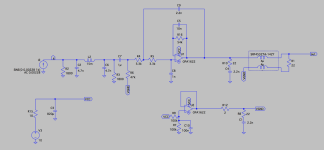
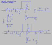
You can get the offset - which is due to the OPA1622's bias current - much lower by equalizing the impedances at the two input terminals. At present the +ve input sees about 54kohm and the -ve input, about zero. So a 56k feedback resistor in place of the wire between OP and -ve input, bypassed by a cap (10nF should do) would go a long way to reducing the output offset. At least should get it below 10mV.
As for the virtual GND, what's the maximum current needed to source/sink into the virtual GND opamp? Increasing the output impedance by an ohm or two won't be a concern if you need to share current between two virtual GND opamps.
As for the virtual GND, what's the maximum current needed to source/sink into the virtual GND opamp? Increasing the output impedance by an ohm or two won't be a concern if you need to share current between two virtual GND opamps.

That's amazing Abrax. With the 54k resistor across the feedback loop the offset voltage went down to a few microvolts in sim. There is always room to learn the basics.
How can I determine the series resistance needed at the output of each VGND opamp, to ensure that they don't load each other? My regular headphones are low current (64ohm 106dB/mW). But when I finish this I might want to try some IEMs that can take up to 65mA I think (22ohm 100dB/mW).
If resistance of about 1-2ohm would be enough, maybe it would be smart to use smaller common-mode inductors with higher DCR?
With the added feedback resistor and bypass capacitor maybe the shunt resistor and capacitor at the driver's OPA output (R10, C4) are now redundant? Just guessing, I don't fully understand how those work. And as usual I'm begging for minimal parts and PCB space.
I've included a series resistor (10ohm, R15) to the power supply, to further decrease the ripple injected by the opamps into the power supply (an ADC and preamps in the same circuit, which one day I want to show). Is this a complete crime to the OPA's performance?
Thanks a lot again for your support.
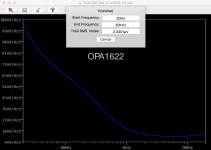
PD.: In attachment the simulation and model OPA1622.lib. It should run if both files are in the same folder.
How can I determine the series resistance needed at the output of each VGND opamp, to ensure that they don't load each other? My regular headphones are low current (64ohm 106dB/mW). But when I finish this I might want to try some IEMs that can take up to 65mA I think (22ohm 100dB/mW).
If resistance of about 1-2ohm would be enough, maybe it would be smart to use smaller common-mode inductors with higher DCR?
With the added feedback resistor and bypass capacitor maybe the shunt resistor and capacitor at the driver's OPA output (R10, C4) are now redundant? Just guessing, I don't fully understand how those work. And as usual I'm begging for minimal parts and PCB space.
I've included a series resistor (10ohm, R15) to the power supply, to further decrease the ripple injected by the opamps into the power supply (an ADC and preamps in the same circuit, which one day I want to show). Is this a complete crime to the OPA's performance?
Thanks a lot again for your support.
PD.: In attachment the simulation and model OPA1622.lib. It should run if both files are in the same folder.
Attachments
How can I determine the series resistance needed at the output of each VGND opamp, to ensure that they don't load each other?
In this application (unity gain) its just down to the offset voltage - assuming both opamps are fed from the same resistor string as reference (R7/R9 junction). Seeing as the worst-case offset is 0.5mV then a 1ohm series R can't have more than 0.5mV across is which represents 0.5mA loading. That's insignificant in this context so you could go lower than 1R but with a total of 0.5R output impedance on the virtual GND (two paralleled opamps) I can't see much point.
I'd not want to increase the CMchoke DCR unless space is truly at a premium however if you can find a smaller one which can handle the current then go for it. I can't see a reason the RC on the output becomes redundant, care to explain your thinking on that? R15 I don't think is a good idea - it'll certainly increase the ripple on the HP amp opamp supply which can't be beneficial. If the ADC and preamps are sensitive then they need their own regulation to deal with that.
All clear, I really appreciate your detailed answer @abraxalito ☕My thinking on the RC at the output being redundant please nevermind, I just thought for a moment that the added resistor and capacitor in the feedback loop would also form an RF protective LPF.
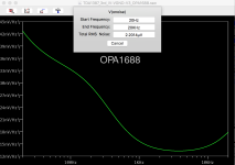
I'm considering more seriously the SOIC OPA1688 now. Since my current demands shouldn't go higher than 70mA I think. I'm a bit scared of dealing with VSON directly these days to be honest, I've never done it before. But also I don't want to get the OPA1622 with adapters like I've done before either. The 1688 is very well priced and it simulates a tad lower in overall noise than the 1622, after the 54K in the feedback loop has been added. It also comes with EMI input filters.
I'm considering more seriously the SOIC OPA1688 now. Since my current demands shouldn't go higher than 70mA I think. I'm a bit scared of dealing with VSON directly these days to be honest, I've never done it before. But also I don't want to get the OPA1622 with adapters like I've done before either. The 1688 is very well priced and it simulates a tad lower in overall noise than the 1622, after the 54K in the feedback loop has been added. It also comes with EMI input filters.
I've not used OPA1688 but have tried OPA1678 which has quite similar LF noise characteristics and I found the bass subjectively too weak. This was during my development of the Kubelik DAC - I eventually settled on OPA2209 for that but it won't suit your application which needs a beefy OPS. A low level of noise in the LF seems to me to be important to get good sounding bass.
Good to know, probably the reason why I find bass absent with opamps usually. I thought it was mainly due to THD.
I could also take the risk with hand soldered VSON... soldering the pins first with a heat gun and the thermal pad underneath after with a soldering iron, through a big enough via. Maybe it'll be easier than it seems.
Strange enough though the OPA1622 plots quite noisy in Spice. Noisier than the OPA1688 or the OPA1656 at the output of this circuit for instance, especially at lower frequencies.
Attachments
Increasing the value of the 10n cap at the feedback loop to 4.7u seems to lower the noise considerably.
Good catch, when I estimated the 10n value I wasn't paying attention to noise. Go for a big enough value to keep the noise down.
Shall this be a bipolar film cap (ie. 4.7u MKS2)? Or X7R ceramic or polar elco would also be ok?
I'd not recommend an X7R as they're microphonic, meaning vibrations get turned into electrical signals. A film cap would be fine (though bulky) or perhaps a tantalum for tiny footprint? If the latter we'd need to know which way the current flows to establish the correct polarity. The DS for the OPA1622 states that the bias current is positive which I take to mean into the chip. So the +ve terminal of the cap will go to the output pin.
We are ready now I think 🍻 Since the circuit will take part in a broader system it might not make sense to share only a PCB layout section here, but once I have it working I'll report my impressions on the sound to the very least. Quite a mentorship @abraxalito!
Attachments
- Home
- Source & Line
- Digital Line Level
- Building a portable I2S 4x TDA1387 DAC