Adrculda said:OK..
since were on the transformers side...
Looking at common amplifiers and such as this one and knowing how important of a role both voltage and amperage are, would it better to get a higher voltage and less amperage or lower voltage and higher amperage ??
X number of watts at Y ohms requires Z volts on the DC rail under load of A1 amperes. The math will fill in all the numbers, but the relationship is fixed. Even of you start out with a trafo that's rated at twice the VA that simple math dictates it still drops some under load and that must be accounted for or you won't get full power. Bigger trafos (more VA, therfore current at a fixed V) tend to drop less than smaller ones, but the differences are not as great as you might think. For amps that will always drive very low impedance, it's generally better to use the lowest voltage you can and still get full power under load. That usually means oversizing in the VA department. For amps driving a variety of loads, a lower regulation unit is peferred, as it will drop to the target voltage at full load, but remain a bit higher driving light loads (so 8 ohm power won't drop by a factor of 4 compared to 2 ohm).
and the amount of AC current in the windings is proportional to the amount of AC flux in the core.
No. For a specific transformer, flux is only dependent on voltage and frequency, see:
http://en.wikipedia.org/wiki/Transformer#Induction_law
Did you read the rest of the page? Did you understand it?
Off that page:
The universal transformer equation indicates a minimum cross-sectional area for the core to avoid saturation.
From the 1st page of an EE text on electric machinery; "Practically all transformers and electric machinery use magnetic material for shaping the magnetic fields which act as the medium for trasfering and converting energy."
FARADAYS LAW
The voltage induced across the secondary coil may be calculated from Faraday's law of induction, which states that:
Vs=Ns d?/dt
where VS is the instantaneous voltage, NS is the number of turns in the secondary coil and ? equals the magnetic flux through one turn of the coil.
Current does not matter, the MMF of secondary and primary cancels.
This is wrong: (and basic physics) Amperes law shows that (moving charge) current produces magnetic flux not voltage. The ? in frdy law is proportional to the current, more CURRENT =more mag. flux (?) = more power transfer. (and I hope you know by current, I mean current change ie AC current)
cbdb said:
This is wrong: (and basic physics) Amperes law shows that (moving charge) current produces magnetic flux not voltage. The ? in frdy law is proportional to the current, more CURRENT =more mag. flux (?) = more power transfer. (and I hope you know by current, I mean current change ie AC current)
No it's right.
Ampere's law too but you are forgetting that there are two windings with current flowing in opposite directions.
Apply it to both secondary and primary. MMF cancels as currents flow in opposite directions => no net flux contribution.
The difference in mmf between primary and secondary falls over the core however. The difference in mmf causes/is caused by the magnetizing current.
This mmf is related by the dimensions of the core and the BH loop to the flux. The flux is proportional to the integral of voltage.
How many transformers have you designed?
Where do you start?
megajocke said:
Current does not matter, the MMF of secondary and primary cancels.
Or, more correctly, the MMF of the secondary load current and the induced primary current cancel. Leaving a net MMF in the primary of exactly what was needed to magnetize the core in the absence of a load.
The whole reason trafos work the way they do is by attempting to keep the effect of the primary magnetizing current the same. By adding MMF due to the load current, an additional current which produces the opposite effect must be induced in the primary. I think this concept is confusing our young friend.
That is a very good explanation wg_ski! 🙂
The reason primary current increases when secondary is loaded is that the load on the secondary makes the secondary try to oppose the magnetic flux through the core.
But if the flux through the core were to decrease then induced voltage in the primary would also decrease - increasing the current through the primary.
The current then increases to cancel the magnetic field from the secondary. And keep flux so that induced voltage cancels the applied voltage.
But I usually think of it in the other direction, with flux/voltage as cause and mmf/current as effect. Makes it much easier to understand IMO.
Wilkipedia:
Can you explain these facts.
andSaturation limits the maximum magnetic fields achievable in ferromagnetic-core electromagnets and transformers to around 2 T, which puts a limit on the minimum size of their cores. This is why high power utility transformers are so large.
By operating at higher frequencies, transformers can be physically more compact because a given core is able to transfer more power without reaching saturation
Can you explain these facts.
It's a very indirect relationship.
Let's say for a given transformer frequency is doubled and the transformer input voltage was saturation limited and not core loss limited.
This means flux will halve if the number of turns is kept the same and input voltage is unchanged.
But this would mean the transformer is only running at half its saturation flux density.
Thus input voltage can be doubled at the doubled frequency to get back the original flux density.
The wires are still the same so resistances are the same => same loss at a specific current.
A transformer of a given size can dissipate a given amount of power (this is where the power transfer limitation comes from) so now we have the same current output as earlier but the output voltage is double => double the power can be transferred for the same power loss and temperature rises.
Which means if we wanted the original power transfer ability, we could have started with a smaller transformer which would have half the intended voltage rating and half the intended power rating at the original frequency.
In reality power transfer ability isn't proportional to frequency, it rises slower because the whole flux swing can't be utilized at higher frequencies because of core loss. But transferable power still increases with frequency.
Thus input voltage can be doubled at the doubled frequency to get back the original flux density.
I thought the the flux density was zero?
And dosnt this also double the current?
Current does not matter, the MMF of secondary and primary cancels.
cbdb said:
I thought the the flux density was zero?
If it were zero at idle no voltage would be induced in primary which would mean lots of current would flow in primary, only limited by winding resistance.
If flux were constant at zero even when idle there wouldn't be any secondary voltage either.
Just like there are voltage and current in the electric circuit there are two quantities in the magnetic circuit: flux and mmf. Flux passing through a loop of wire induces voltage into it according to Faraday's law while current flowing through a loop causes a mmf between it's sides.
But there aren't really any causes and effects in electromagnetics so it might as well be reversed:
The applied voltage causes just enough flux to cancel it. Any deviation would change the current in the primary to make this true.
The same flux induces voltage in the secondary.
I dont understand why you cant agree that a transformer core will limit the amount of power you can transfer with it becuase of magnetic saturation. Look it up.
Probably because it's wrong and it doesn't.
Flux is fixed independent of current because otherwise the balance between induced voltage in primary and applied voltage wouldn't add up any longer.
Induced voltage in primary = dFi/dt * N
If resistance is neglible then:
Induced voltage = Applied voltage
which means:
applied voltage = dFi/dt * N
(there is no cause and effect, the relation works both ways)
But in this case applied voltage is the driving force so integrating gives:
Fi = Integral(applied voltage*dt) / N
Observe that both Fi and applied voltage are functions of time!
I'm sure I want to get involved in this, but here I go.
megajocke is correct.
To attempt to put things in simple terms (which isn't easy with magnetics), look at the transformer when power is first applied. There is an inrush of current as the core builds up flux density. When the core is sufficiently saturated, almost all current stops flowing in the primary. If you now load the secondary, reducing the flux density in the core, current will again flow in the primary. This is why you can load a transformer well beyond its rated power for short times. Power delivered is not limited by core saturation.
Now if we go back to the point after the inrush current and raise the voltage or lower the frequency, the transformer will get hot and noisy very fast. This is because you have pushed the core to saturation and the extra energy the transformer draws goes into loses.
You still havent explained:
Wilkipedia:
quote:
Saturation limits the maximum magnetic fields achievable in ferromagnetic-core electromagnets and transformers to around 2 T, which puts a limit on the minimum size of their cores. This is why high power utility transformers are so large.
and
quote:
By operating at higher frequencies, transformers can be physically more compact because a given core is able to transfer more power without reaching saturation
The Wikipedia explanation isn't wrong but it doesn't tell you how indirect the relationship is. Saturation sets the limit on the minimum amount of turns needed for a specific voltage at a specific frequency. If frequency is increased for the same transformer core fewer turns are needed which means thicker wire that can take more current will fit.
See the previous post: http://www.diyaudio.com/forums/showthread.php?postid=1734588#post1734588
For a given transformer, without changing anything in the transformer itself: The power dissipation in the windings is what limits output power, so the current the transformer can deliver is the same but at double the voltage at double frequency. Result: Double power can be transferred. (In reality a bit less because core losses increase with frequency)
The opposite is also true, if frequency is halved voltage has to be halved too or the transformer will saturate like Steve Dunlap says.
Thus at halved frequency only half the power can be transferred.
Heres my short explanation. MMF, and magnetic flux are two different things (but related thru magnetic permeability). Sort of analogous to EMF, current and resistance. When running power the ideal transformer (permiability is infinte) MMF canncels but there is still lots of flux (like a shorted battery, no voltage, lots of current) If you run too much flux thru the core, it will saturate wich drops the permeability and limits the flux. (the wire shorting the battery heats up adds resistance and limits the current (sort of))
But flux through windings is fixed by the relationship:
Vin(t) = dFi/dt(t) * Npri
The difference in MMF between primary and secondary (magnetizing current) is a consequence of this and gets higher the lower permeability the core has.
If you take a wire loop (your shorted secondary) and put around the flux path a current will be induced - but it will tend to oppose the flux change, not reinforce it.
It's called Lenz Law and one of the more obvious ones:
http://en.wikipedia.org/wiki/Lenz's_law
If it did reinforce it the universe would blow up and that would be bad IMO... 😀
Lenz's Law is one consequence of the principle of conservation of energy. To see why, move a magnet towards the face of a closed loop of wire (eg. a coil or solenoid). An electric current is induced in the wire, because the electrons within it are subjected to an increasing magnetic field as the magnet approaches. This produces an emf (electro motive force) that acts upon them. The direction of the induced current depends on whether the north or south pole of the magnet is approaching: an approaching north pole will produce an anti-clockwise current (from the perspective of the magnet), and south pole approaching the coil will produce a clockwise current. To understand the implications for conservation of energy, suppose that the induced currents' directions were opposite to those just described. Then the north pole of an approaching magnet would induce a south pole in the near face of the loop. The attractive force between these poles would accelerate the magnet's approach. This would make the magnetic field increase more quickly, which in turn would increase the loop's current, strengthening the magnetic field, increasing the attraction and acceleration, and so on. Both the kinetic energy of the magnet and the rate of energy dissipation in the loop (due to Joule heating) would increase. A small energy input would produce a large energy output, violating the law of conservation of energy. This scenario is only one example of electromagnetic induction. Lenz's Law states that the magnetic field of any induced current opposes the change that induces it. For a rigorous mathematical treatment, see electromagnetic induction and Maxwell's equations.
Still OT...
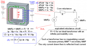
Picture showing relation between the MMF, flux, reluctance and the electric circuit.
Also shows where MMF is physically located in a fictional transformer with primary and secondary separated. If windings are wound over each other then large MMF differences only exists in the windings themselves making leakage inductance much lower.
In the shown structure the MMF between upper and lower part of core will drive some flux through the air which creates lots of leakage inductance. This isn't shown in the picture though.
Attachments
I think this Thread should be a good read for all the newbies.
Very informative and has a lot of options for those that want to build something them self.
Lots of info on power supply, amplifying circuit detail, driver and output transistor selection AND its actual operation.
This Transformer discussion might have been off-topic but informative for those that don't exactly know what they are getting into.
megajocke is right.
Transformers with reasonable VA ratings are best and can handle any power for any time (until the windings melt 😀) Also, when load impedance is lowered it's usually better to have sagging rails, or said in another way, higher rails and more power at higher impedances.
Professional amplifiers are designed that way, the clever way, they wouldn't achieve reasonable size and weight otherwise. Overkill is for freaks.
With rails higher than +/-75V, Class G/H switching or class D is required in order to get power losses under control and achieve reasonable size/weight.
The latest class D stuff achieves power eficiencies over 90% from the wall outlet to the speaker at over 1KW.
Look for AB International 1100A or 9620 schematics, these are amplifiers with +/-60V and +/-120V rails and an interesting yet simple rail switching scheme that allows the rails to fall to ground to better handle reactive loads.
- Status
- Not open for further replies.
- Home
- Amplifiers
- Solid State
- Building a Monster... Class A