Hi All,
Hoping to get some help with building a high voltage SMPS.
I have built up the circuit shown here http://diyaudioprojects.com/Tubes/12AX7_Preamp/F02psschematic.jpg using the TL494. The only changes I made are a larger inductor which I had to hand.
The power supply seems to be working OK, but it takes a very long time to get up to voltage - about 5 minutes. And it gets up to about 260V and at that point the HT adjust no longer makes a difference.
It also only gets up to this voltage with no load, with a load it hardly makes it over 30V.
Would someone be able to suggest a solution for the slow ramp up and what might be causing the problem? I do not really know a lot about these types of power supply, but thought the best way to learn was to build it!
Also, if this circuit is not a good performer, maybe someone has a better tried and tested one?
Many thanks
Charlie
Monitor the 12V line to see if it is always there during ramp-up.
What load did you put on it?
Did you build it with exactly the same part values?
What is the frequency that the 494 is running? (39K / 1nF should get you 30KHz)
Any pix?
What load did you put on it?
Did you build it with exactly the same part values?
What is the frequency that the 494 is running? (39K / 1nF should get you 30KHz)
Any pix?
The 12V is constant from turn on.
I built it with the same values, apart from the smoothing choke which is a 300mH inductor I had to hand.
Not much to look at but maybe this will show any issues. I built it to fit in quite a small enclosure, which may of been an error. However nothing is getting too hot so far.
Is 30KHz too low? many supplies I have read up on using the 494 have been in the 100kHz region.
Thanks for your input
Charlie
Attachments
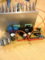
The drawing calls for an ETD-29 core to be wound as an auto transformer with 12 turns input and 80 turns output. I do not see this transformer in your picture, but it looks like you have 2 pieces of 300mH inductors. I suspect you substituted these 2 inductors for the ETD-29 transformer.
The two coils need to share the same magnetic core, as you are using two separate cores the circuit can't work.
Basically when the MOS-FET is ON it builds up flux in the core via the 12T coil. When the MOS-FET turns OFF the field collapses and causes a high voltage to be generated in the 80T coil.
So the core must be common and it must also be of the correct size, grade and type.
Basically when the MOS-FET is ON it builds up flux in the core via the 12T coil. When the MOS-FET turns OFF the field collapses and causes a high voltage to be generated in the 80T coil.
So the core must be common and it must also be of the correct size, grade and type.
Last edited:
I hope you used the recommended high frequency schottky diode as D2. A simple 1N4004 wont work here either.
OK thanks for bringing me up to speed, as I said I didn't really understand tha circuit so built it to see what was going on.
I had the 300mH to hand because I was going to build this circuit by Pete Millett http://www.pmillett.com/file_downloads/micpre_sch.pdf but opted out because I didn't want to use the 48V input.
My mistake was assuming that the choke in Pete's circuit was just for smoothing. I actually shorted the second choke (80T) to see if it made any difference but it didnt.
So my question would be, why does the original posted circuit need two chokes and Pete Millett's circuit only need one? Also, the idea of winding my own isnt really convenient for me so would really welcome an suggestions to changing the circuit I have built to make it work..... if that is possible.
I followed all component recommendations apart from the choke, and I used overated components because I was unsure. It does state D2 as UF4004, I used UF4007.
Good to know it didn't cause fireworks!
Cheers
Charlie - still learning
I had the 300mH to hand because I was going to build this circuit by Pete Millett http://www.pmillett.com/file_downloads/micpre_sch.pdf but opted out because I didn't want to use the 48V input.
My mistake was assuming that the choke in Pete's circuit was just for smoothing. I actually shorted the second choke (80T) to see if it made any difference but it didnt.
So my question would be, why does the original posted circuit need two chokes and Pete Millett's circuit only need one? Also, the idea of winding my own isnt really convenient for me so would really welcome an suggestions to changing the circuit I have built to make it work..... if that is possible.
I hope you used the recommended high frequency schottky diode as D2. A simple 1N4004 wont work here either.
I followed all component recommendations apart from the choke, and I used overated components because I was unsure. It does state D2 as UF4004, I used UF4007.
Good to know it didn't cause fireworks!
Cheers
Charlie - still learning
Last edited:
The OP circuit has ONE choke with two windings. You could try hunting through the bins to see if you can find a reasonable sized toroidal core, but you will need to wind your own choke with the turns specified. (In reality the ratio of the turns coupled with the magnetising force required to saturate the core which are important but as you wont know the reluctance of the magnetic core you can but experiment.)
Last edited:
Well those links don't seem to work.
Just go onto E-Bay and enter ETD29. You need one bobbin, two E core pieces and two clips that hold it together. Item numbers 140941907975, 360622945133 and 130876999370
You will also need a few meters of enamelled copper wire. Hopefully the data with your schematic will give you some idea of the gauge of the wire required. The whole choke should cost less than a tenner.
If you are not familiar with E-Bay just enter the item number in the search box and each item will come up in turn. They are all from the same supplier and P&P is FREE.
Last edited:
The circuit which you are trying to build is called a "Boost Converter".
see: Boost converter - Wikipedia, the free encyclopedia
To work at the desired frequency and voltage the boost inductor needs to be in the range of 100 micro-henry, not milli-henry.
The 12-T winding is the boost inductor in your example, which also acts as the primary in what is actually an auto-transformer on the EDT core. The 80-T winding is the secondary.
They have done this because it is difficult - though doable with limited efficiency and for small currents - to boost from 12v to 250v in one step.
see also: http://www.diyaudio.com/forums/tubes-valves/202151-12-volt-300-volt-inverter-question-tubes-2.html
Last edited:
Sorry, was busy with work.
Thanks for all the comments, I did actually read that other read but obviously not very well as there are some great circuits on there. I will certainly give them a go.
My reason for not wanting to wind my own is because I have never done it before and would not really know where to start. But I am sure there are some guides online to work through.
As I have already built this circuit it will be worth making the choke and comparing it to another circuit.
I read that the harmonic content of 494 circuits is not as good as others, has anyone found this too?
Many thanks
You already have a significant load on the output.
The ~2M of resistor ladder draws ~120uA, ~30mW
The ~2M of resistor ladder draws ~120uA, ~30mW
You should experiment with the circuit you have built already.
Remove or short out the second inductor, it should immediately improve the output.
Replace the 39k timing resistor with a 100K potentiometer, so you can very the frequency of operation.(The inductor and the frequency are directly related)
You may get an understanding of the limits of what you are trying to do.
- Status
- Not open for further replies.
- Home
- Amplifiers
- Power Supplies
- Building a high voltage SMPS