I've been using the Tripath based (41Hz modules) car amps I built for several years now. Time for an upgrade.
I bought these UcD180HG modules back in May last year but never worked on it as I can't decide on which route to take on the powersupply and chassis. DIY? off the shelf? modules?
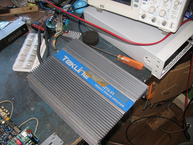
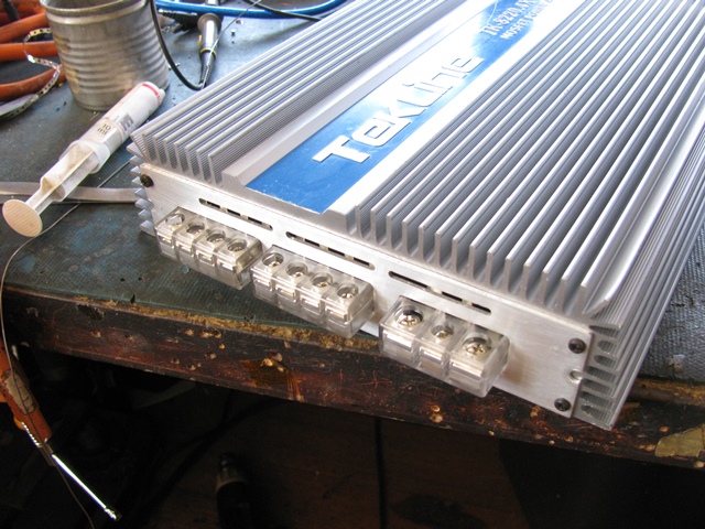
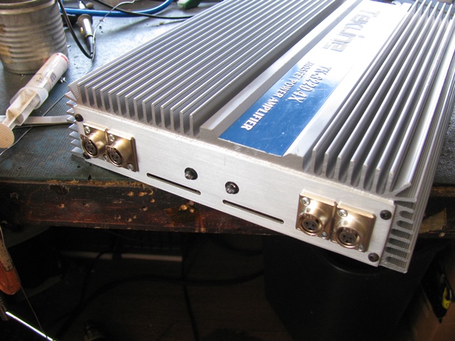
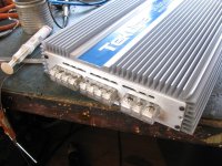
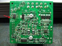
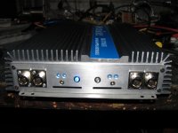
Suddenly dawned on me that an off the shelf car amp would be a good way to have most of the difficult parts already done. Looked at the bunch of car amps I got from a local repair shop for a good one and ended up with a generic one from the 90's.
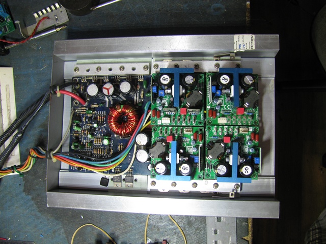
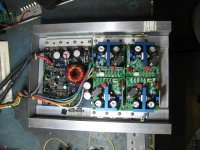
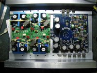
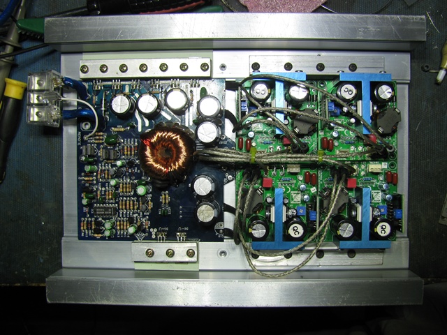
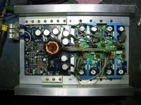
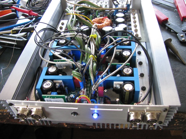
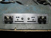
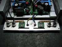
Took the bottom plate off and the four UcD180HG modules fit in it like a glove.
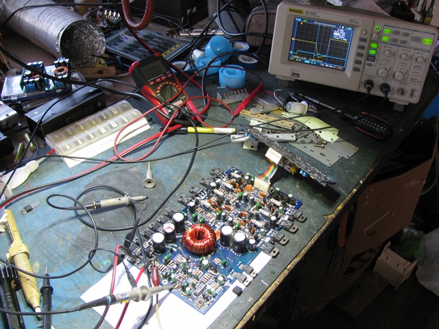
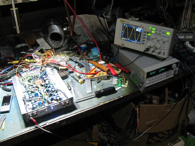
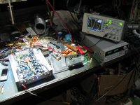
Testing the powersupply and looking for the signals for DC protect, overcurrent and delayed mute signal. Which, luckily, can very easily be integrated for use with the UcD modules!
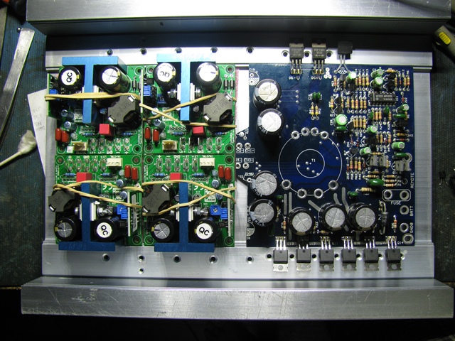
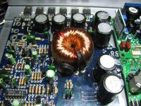
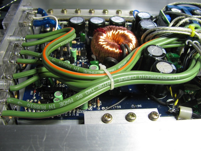
Powersupply chopped off, cleaned and replaced stuff to handle the higher power this will be designed for. And it still fits, barely.
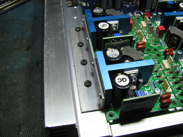
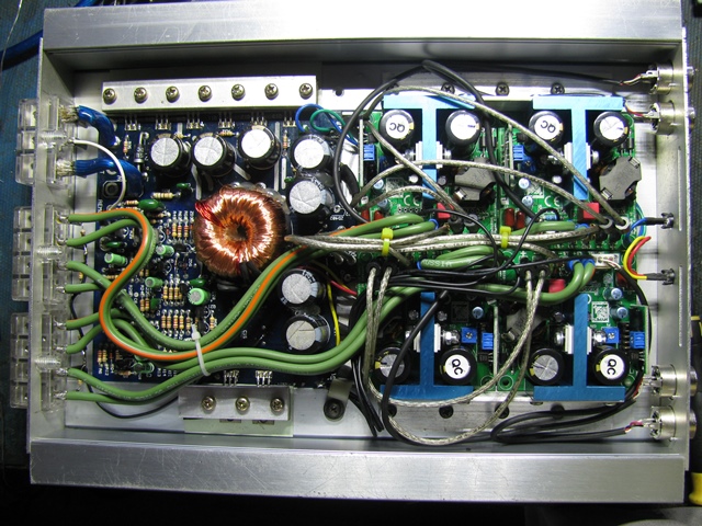
Original powersupply fets are IRFZ30. Replaced them with IRF3205, changed the 220ohm gate resistors to 22ohms and changed the driver transistors for higher current. Transformer will be rewound for higher output voltage and more copper for more current.
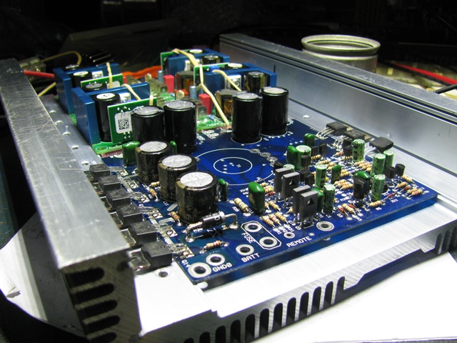
Original gate drive transistors were the 100mA rated C1815/A1015 transistors. Replaced them with BD139/140 pairs which have the same pinout in the PCB
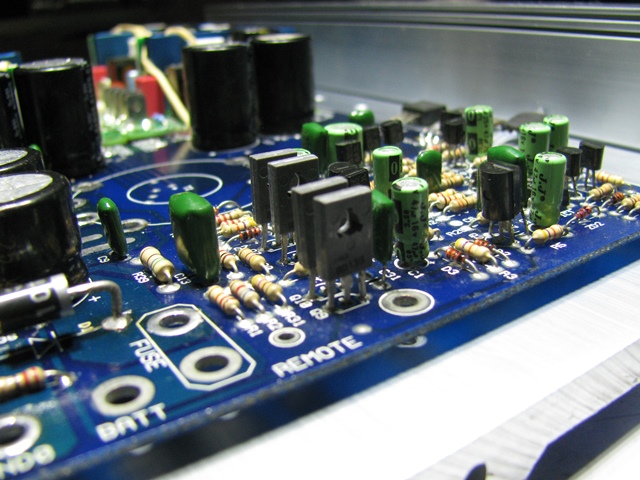
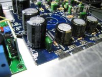
Replaced the powersupply caps with Elna/Rubycon since I didn't like the old no name caps which won't survive the expected higher rail voltages anyways.

I'll update this thread as the project progresses. I also posted it in my site with a few more pictures too.
I bought these UcD180HG modules back in May last year but never worked on it as I can't decide on which route to take on the powersupply and chassis. DIY? off the shelf? modules?
Suddenly dawned on me that an off the shelf car amp would be a good way to have most of the difficult parts already done. Looked at the bunch of car amps I got from a local repair shop for a good one and ended up with a generic one from the 90's.
Took the bottom plate off and the four UcD180HG modules fit in it like a glove.
Testing the powersupply and looking for the signals for DC protect, overcurrent and delayed mute signal. Which, luckily, can very easily be integrated for use with the UcD modules!
Powersupply chopped off, cleaned and replaced stuff to handle the higher power this will be designed for. And it still fits, barely.
Original powersupply fets are IRFZ30. Replaced them with IRF3205, changed the 220ohm gate resistors to 22ohms and changed the driver transistors for higher current. Transformer will be rewound for higher output voltage and more copper for more current.
Original gate drive transistors were the 100mA rated C1815/A1015 transistors. Replaced them with BD139/140 pairs which have the same pinout in the PCB
Replaced the powersupply caps with Elna/Rubycon since I didn't like the old no name caps which won't survive the expected higher rail voltages anyways.
I'll update this thread as the project progresses. I also posted it in my site with a few more pictures too.
Attachments


Last edited:
Thanks, I actually bought 5 modules. I wanted to keep a spare incase something bad happens. (I hope not!)
Input connectors will be mini XLR jacks. This will be driven by my DCX2496 in the car so no problem with balanced sources. (The DCX is also driven off my DIY line driver with balanced signals)
My concerns with this build is the modules are close to each other which might make interference issues. And also the bus pumping issue (which may be circumvented by running each channel pair out of phase - easily done since I have a balanced source).
Did a bit more work tonight...
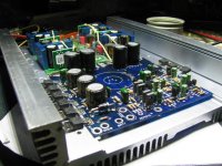
Rewound the transformer secondary for 50V rails. Used DIY litz wire with 40 strands of #31 wire.

Angle bracket to hold the hypex modules
Wired up the power supply lines. I ran out of wires to connect the speaker terminals to the amp modules.
Now I need some alu sheet to make the end plates.
Rewound the transformer secondary for 50V rails. Used DIY litz wire with 40 strands of #31 wire.
Angle bracket to hold the hypex modules
Wired up the power supply lines. I ran out of wires to connect the speaker terminals to the amp modules.
Now I need some alu sheet to make the end plates.
Attachments

Amp is now installed in the car. Very nice sounding except for a loud turn on pop. Other than that, my concern regarding the switching frequencies interacting with the multiple modules did not occur, it is dead silent. Just need to add an attenuator. Gain is too high for my use.
I'll post pics later once I tidy up the install
I'll post pics later once I tidy up the install
Here are some more pics!
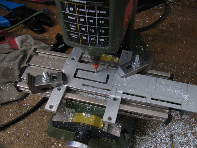
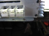
Used my micro mill to cut the rectangular holes for the terminal blocks.
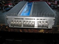
End panels finished:
And it lives!!! No fireworks!
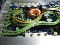
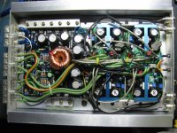
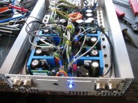
Here's the rats nest
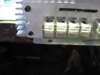
Tchernov audio speaker wires used to connect the UcD180HG modules to the terminal blocks
Design fail. Terminal blocks ended up covering the mounting holes.
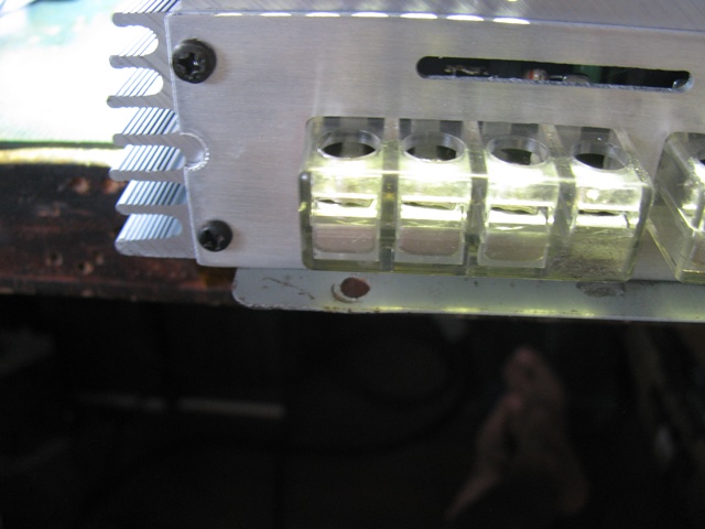

Ended up drilling new mounting holes.

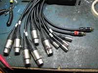
Canare Star Quad cables with Neutrik XLRs, Switchcraft mini XLRs to connect the amp to the DCX2496.

Used my micro mill to cut the rectangular holes for the terminal blocks.
End panels finished:
And it lives!!! No fireworks!
Here's the rats nest
Tchernov audio speaker wires used to connect the UcD180HG modules to the terminal blocks
Design fail. Terminal blocks ended up covering the mounting holes.
Ended up drilling new mounting holes.
Canare Star Quad cables with Neutrik XLRs, Switchcraft mini XLRs to connect the amp to the DCX2496.
Attachments
-
 IMG_1369.jpg198.1 KB · Views: 227
 -
 IMG_1366.jpg132.3 KB · Views: 214
 -
 IMG_1365.jpg93.7 KB · Views: 215
 -
 IMG_1364.jpg92.4 KB · Views: 220
 -
 IMG_1362.jpg161.9 KB · Views: 240
 -
 IMG_1353.jpg193.2 KB · Views: 248
 -
 IMG_1352.jpg180.8 KB · Views: 223
 -
 IMG_1349.jpg153.1 KB · Views: 220
 -
 IMG_1348.jpg170 KB · Views: 228
 -
 IMG_1346.jpg165.7 KB · Views: 239
wwwoww...that's just...grreaat!!
how's the tchernov sounds?..i'm considering to use them but idk how they sounds
anyway, the popping sound might from the PSU..you can use output delay or maybe softstart(?)
oh..i forgot something..
how's the heat of the toroid?..they looks a little bit too small after rewound
how's the tchernov sounds?..i'm considering to use them but idk how they sounds
anyway, the popping sound might from the PSU..you can use output delay or maybe softstart(?)
oh..i forgot something..
how's the heat of the toroid?..they looks a little bit too small after rewound
flawless work !!
thanks!
Very nice!!! Would love to hear that amp in use.
You're welcome to come over but the plane ticket ain't cheap
wwwoww...that's just...grreaat!!
how's the tchernov sounds?..i'm considering to use them but idk how they sounds
anyway, the popping sound might from the PSU..you can use output delay or maybe softstart(?)
oh..i forgot something..
how's the heat of the toroid?..they looks a little bit too small after rewound
I also used Tchernov cable on my home P101 amp. I don't know if it has an effect but the amp does sound great
I was able to fix the popping sound by adjusting a resistor value so that the amp unmutes well past when the DCX boots up. Now it's just a faint "tick" on the tweeters.
The transformer holds up just fine. The other two channels only drive the tweeters so there's not much strain on the PSU.
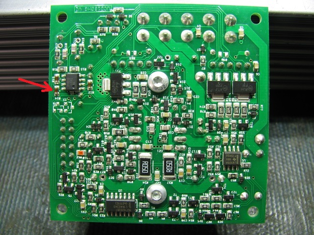
I also reduced the gain of the UcD modules from 21X to just 4.5X (by removing a resistor on the op amp stage on the Hypex module) and it's still a little high but can be tamed. Sounds even better now.
Some more....
To change the delay I increased this resistor (originally 47k) to 330K to increase the unmute time to about 3.6sec. Well beyond the boot up time of the DCX2496. Pretty much solved the pop issue
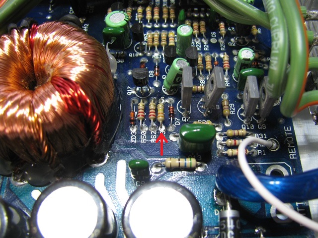
And I removed this resistor to decrease the amp gain from 21dB to 13dB. Still a little high but can be managed by the DCX2496 gain adjustment to tune for driver efficiencies. I could have used an attenuator on the input but that would put more parts in the signal path (and we know what happens if you do that )
)
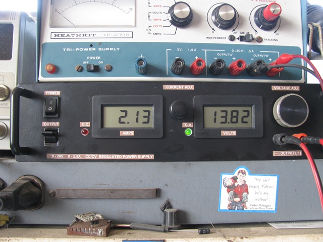
current draw on the test bench. Since I'm using a regulator, I'm pushing 14.6V into the amps no matter what the battery voltage is. At that voltage, idle draw is about 2.35A with 50V rails. (rail voltages are 45V at 13.2V input, 42V at 12.6V input)
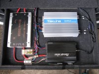
rearranged the amprack wiring to make things look neater

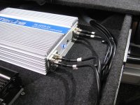
mmmm, balanced inputs

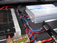
amprack overhead view. Where is the DIY amp?

To change the delay I increased this resistor (originally 47k) to 330K to increase the unmute time to about 3.6sec. Well beyond the boot up time of the DCX2496. Pretty much solved the pop issue
And I removed this resistor to decrease the amp gain from 21dB to 13dB. Still a little high but can be managed by the DCX2496 gain adjustment to tune for driver efficiencies. I could have used an attenuator on the input but that would put more parts in the signal path (and we know what happens if you do that
)current draw on the test bench. Since I'm using a regulator, I'm pushing 14.6V into the amps no matter what the battery voltage is. At that voltage, idle draw is about 2.35A with 50V rails. (rail voltages are 45V at 13.2V input, 42V at 12.6V input)
rearranged the amprack wiring to make things look neater
mmmm, balanced inputs
amprack overhead view. Where is the DIY amp?
Attachments


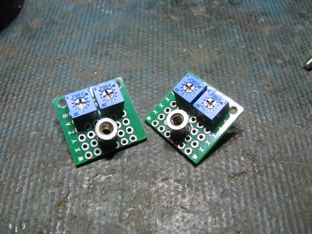
I found out the hard way that a gain control is a necessity. So I figured out a way to put one in the amp.
Made a couple ones mounted on perf board using the sealed Bourns 3362 trimmers.
Installed in the input panel. (I measured twice, drilled once. And it still came out misaligned. It's not too obvious though)
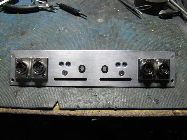
Back side. The resistors behind the mini XLR jacks are 10K 0.1% 25ppm. I got them from a scrap PCB which has a bunch
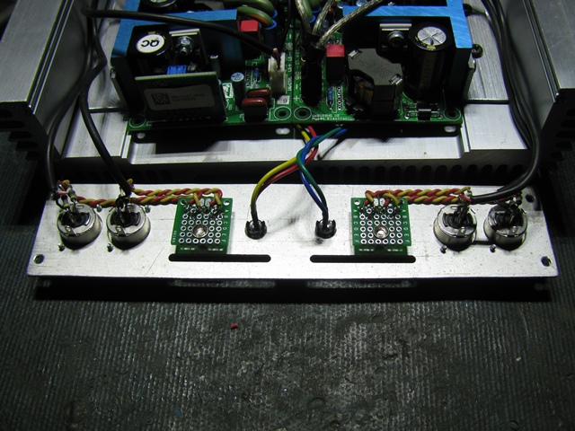
Setting the gain to be the same as my old amps so I can reuse the old preset in the DCX2496
Input panel with gain control

Made a couple ones mounted on perf board using the sealed Bourns 3362 trimmers.
Installed in the input panel. (I measured twice, drilled once. And it still came out misaligned.
It's not too obvious though)Back side. The resistors behind the mini XLR jacks are 10K 0.1% 25ppm. I got them from a scrap PCB which has a bunch
Setting the gain to be the same as my old amps so I can reuse the old preset in the DCX2496
Input panel with gain control
Attachments

I bought some in bulk from a manufacturer in alibaba. It was cheap so I got a lot for future projects
http://www.alibaba.com/product-gs/692527984/Barrier_Terminal_Block_EMT_2_Pitch.html
http://www.alibaba.com/product-gs/692609996/Isulated_Barrier_Terminal_Block_EMT_3.html
http://www.alibaba.com/product-gs/692669859/Isulated_Barrier_Terminal_Block_EMT_4.html
http://www.alibaba.com/product-gs/692527984/Barrier_Terminal_Block_EMT_2_Pitch.html
http://www.alibaba.com/product-gs/692609996/Isulated_Barrier_Terminal_Block_EMT_3.html
http://www.alibaba.com/product-gs/692669859/Isulated_Barrier_Terminal_Block_EMT_4.html
Last edited:
- Status
- This old topic is closed. If you want to reopen this topic, contact a moderator using the "Report Post" button.
- Home
- General Interest
- Car Audio
- Building a car amp using UcD180HG modules