Hello, I've got a little experience with electronics(class d amps, microprocessors etc) and I would like to build my own amplifier.
Found this pretty basic budget amplifier circuit that can apparently do 1000w?
Found this pretty basic budget amplifier circuit that can apparently do 1000w?
- Does anyone know the name of this circuit, I've seen quite a few other videos w same design.
- also would I have to use the exact same components because it's fairly difficult to pick up 0.33 ohm ceramic resistors, could I use a different resistor type?
- would it sound any good? I'm planning on using it with a 12" super scoop. I would be amazed if it could push 1000w
1000 watt A/B would have multiple about devices
So for thermal stability and current sharing .33 could be higher
with so many devices. .47 or .68 ohm
keep in mind the voltage involved and transformer
of 2000va would need soft start, and any fault
condition putting DC on the output would instantly destroy
any speaker. So numerous protection is mandatory
.
The video does not include a schematic.
As for 0.33 ohm; 5 W ceramic resistor availability: https://uk.farnell.com/tt-electroni...jlf/wirewound-resistor-0-33-ohm-5w/dp/1457948
As for 0.33 ohm; 5 W ceramic resistor availability: https://uk.farnell.com/tt-electroni...jlf/wirewound-resistor-0-33-ohm-5w/dp/1457948
What circuit? We need some kind of link. 1000W tells us about nothing. Building a huge amp is a classic mistake beginners attempt. After you have some experience, you will probably change your mind, but you have a much better chance of getting it working. Otherwise, expect to give up after wasting a lot of money on expensive parts.Hello, I've got a little experience with electronics(class d amps, microprocessors etc) and I would like to build my own amplifier.
Found this pretty basic budget amplifier circuit that can apparently do 1000w?
- Does anyone know the name of this circuit, I've seen quite a few other videos w same design.
- also would I have to use the exact same components because it's fairly difficult to pick up 0.33 ohm ceramic resistors, could I use a different resistor type?
- would it sound any good? I'm planning on using it with a 12" super scoop. I would be amazed if it could push 1000w

Video states the amplifier is 500W.
1000W for a stereo pair.
Be clear why you want to build this. If it's 'because you can' then knock yourself out.
If you actually want a 1000W amplifier then it will create a lot of heat and consume a lot of power.
Class D is the practical way to go: then only your speakers will get hot.
1000W for a stereo pair.
Be clear why you want to build this. If it's 'because you can' then knock yourself out.
If you actually want a 1000W amplifier then it will create a lot of heat and consume a lot of power.
Class D is the practical way to go: then only your speakers will get hot.
Link to schematic diagram underneath video was not found.
I did read this: "If you are a beginner, we recommend starting with less complex and cheaper projects."
And who needs 1000 W when 100 W RMS into 4 ohm would suffice?
You may like to consider a proven amplifier kit (mono) to cut your teeth on: http://velleman.co.uk/contents/en-uk/p308_k8060.html
I did read this: "If you are a beginner, we recommend starting with less complex and cheaper projects."
And who needs 1000 W when 100 W RMS into 4 ohm would suffice?
You may like to consider a proven amplifier kit (mono) to cut your teeth on: http://velleman.co.uk/contents/en-uk/p308_k8060.html
That amp will not be cheap and being your first amp that you have built, probably not successful.
For the most part.
I tend not to question peoples ability's to much.
But then again, not sure exactly why 1000 watts
is needed.
And even experienced builders might even not be
interested in such a amplifier.
Unless the application absolutely required it.
The amplifier circuits are relatively affordable.
But transformer and power supply and required
safety circuits would very much raise the overall
cost.
Also keep in mind 1000 watts would require
forced air cooling. So the case and wind tunnel
would need to be designed well to be effective.
So if your ok with wind noise, and some commercial
designs play around with fan speed to reduce that.
If for mobile use, there is concerns for durability
and well mounted sub circuits for shocks and
vibrations.
Just stepping up to a 300 watt amplifier has its
endeavors.
Still be fun to see the schematic.
And likewise I have seen some rather
high powered amplifiers built on YouTube.
Well edited and make it appear seem rather easy.
And likewise I have seen some rather
high powered amplifiers built on YouTube.
Well edited and make it appear seem rather easy.
Sorry that the video doesn't include the schematic, I'm drawing one out now based of what I can see in the video.
For all the people saying i should just sit with lower power, i need the 1000w because as I mentioned I'm driving a 12" 700w rms super scoop.
Thanks for the suggestions of buying kits or class d amps however I would really like to build my own, I already have a zk-as21 class d chipamp with 350w subwoofer output, however it's not enough.
Also I have a 900w 0-90v power supply at my disposal so there's no need to worry about the sketchy diy power supply used in the video.
Class D chip amps that claim X watts rarely put out even X/2 watts. 350 real watts may be louder than you think.
Whats this for, some sort of PA system? Scoops are usually used for that, rather than shaking some living room to pieces. In that case, the wattage may be justified. But if you dig into the live sound/PA forums, usually the “pro’s” strongly advise people against building their own amplifiers. The reason TO do it would be to learn, or if you like building amplifiers for the sake of building amplifiers.
But if you want a suggestion as to what kind of amp you could build, look into the Apex A900. It’s an easy to build H-class amp, similar to QSC RMX but without the “inside out” power supply. Properly built, it’s just as good. Uses pretty much generic components, but you WILL need real Toshiba, Sanken, or ON Semi transistors - don’t try to use Aliexpress parts or TIPs. You will end up with a fireball instead of bass.
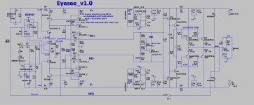
Hi guys, I made a pretty ugly schematic although it should be accurate. Bear in mind that the stage that has 6 transistors and 6 resistors should be much longer, should be 20 transistors and 20 resistors long, just made it smaller for space. The OP amp ic is tl072.
Happy to provide more info


Happy to provide more info
That looks like it will instantly turn into a ball of fire. Start off with a small proven design.
Making a thousand Watt amplifier is no easy task even for a pro.
Making a thousand Watt amplifier is no easy task even for a pro.
Consider building a headphone amplifier first or assembling something from the DIY store. This is about DIY and even these small uncomplicated builds are satisfying.Hello, I've got a little experience with electronics(class d amps, microprocessors etc) and I would like to build my own amplifier.
True. 99% of it is the physical construction, the other 1% is the schematic when it comes to building large amplifiers.
That particular schematic is “too simple” to be safe at the kW level, regardless of the number of output transistors. Looks like the general idea of the QSC PLX or one of the last generation of Crest linear amps, but without most of the refinements needed to keep it from going poof on clipping or overload - and doesn’t address thermal stability. If you want to build something THAT simple it needs to be limited to 20-50 watts per channel.
That particular schematic is “too simple” to be safe at the kW level, regardless of the number of output transistors. Looks like the general idea of the QSC PLX or one of the last generation of Crest linear amps, but without most of the refinements needed to keep it from going poof on clipping or overload - and doesn’t address thermal stability. If you want to build something THAT simple it needs to be limited to 20-50 watts per channel.
The circuit is working for him because it has no bias, horrible crossover distortion and he is running it at a couple of Watts.
Having designed, built and sold one thousand Watt amplifiers that isn’t one I can assure you.
Having designed, built and sold one thousand Watt amplifiers that isn’t one I can assure you.
No 1KW out of that.... TL072 driving (that?) ??? Not enough current gain / no fidelity. (Below 1) shows all the support circuitry to get any descentHi guys, I made a pretty ugly schematic although it should be accurate. Bear in mind that the stage that has 6 transistors and 6 resistors should be much longer, should be 20 transistors and 20 resistors long, just made it smaller for space. The OP amp ic is tl072.
fidelity out of a TL072 (20-30ppm/.003%).
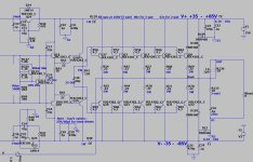
It's actually easier to design/build a fully discrete circuit. Badger/wolverine current- sourced design is a better bet running a 5 pair EF3 (triple).
For anything running 10 pair outputs , your drivers would need to be outputs ... as well.
Just to show you (below 2) , 5 pair EF3 done properly - just add 5 more pairs (and a 1KVA 90V rail PS).
PS - a lot of expensive parts , I don't see how it could be "budget" ??
OS
Attachments
These internet videos are barely more than the "free energy" videos in that their purpose is not to make anything useful, but to collect sponsor revenue, ie click bate. These hand wired point-point circuits never make it off the test bench and do not work well enough to risk your speakers. Making something that works marginally for 5 minutes is not the same as making a real amplifier. The audio market has a lot of "audiophile" products of dubious value, but these internet videos are not even that useful. 50+ years ago, hackers did this sort of thing with vacuum tubes, but it was harder to destroy tubes and the power was limited to about 50 Watts.
- Home
- Amplifiers
- Solid State
- Building a budget amplifier