Hi folks,
i had read the threads over low-jitter clocks and found it very interesting. however, i think there is still room for further improving and i will try it. unfortunately i have no experience with quartz-oscillator circuits until today. so the development could take some time...
first of all, essential for a low jitter clock is a very low noise power supply.
here are some possibilties:
op-amp based voltage regulator like in LClock XO3
- poor hf ripple rejection
- load regulation is much too slow
emitter followed shunt regulator like in KWAK-CLOCK-7
- poor noise performance and hf ripple rejection
- load regulation is much too slow
simple 3 pin regulator:
- poor noise performance and hf ripple rejection
- load regulation is much too slow
- nf ripple rejection could be better
(propably the best in this aspect is the NJM7805FA not the lt1086!!
LT1086 Ripple -68dB Unoi @ 5V: 150 µV
NJM 7805FA Ripple -78db Unoi @5V: 45 µV
or in smd: kf50)
next problem: even the best regulator could not be cleaner than the ground he sees. therefore big loads to the ground planes should be avoided. if you have a large c at the input, his ripple current pollutes the ground or alternatively when he is separately grounded to the main supply, he is quiet useless because of long wires and the already big main supply c's.
so what we need is a circuit, which has great low frequencies ripple recejtion (cause no big C's are used), has very little noise, low output impedance at high frequencies (cause we have no lf-loads fluctuations) and then improving the hf performance with r/l/c-filters. the voltages for the oscillator and the comparator must be carefully decoupled.
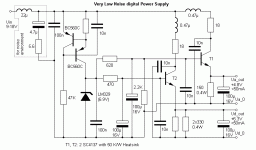
i designed such a circuit for a modiefied kwak-clock. the voltage for the comparator is 6.3V, cause of the saturation voltage of 1.5V (max clock out = (typ) 6.3 - 1.5 = 4.8V).
power supply related modification of the kwak-clock-7
negative voltage is not necessary if a small positive voltage is given to the + input and the 2 K Poti is connected to the ground instead of R11.
maybe C13 and R12 coud just removed. what voltages is on R1 ?
possible further improvements:
- the comparator should have some positive feedback for improving performance
- what is the hf outpult voltage at the source (R1) ? maybe a j-fet amp could improving noise performance...
comments or suggestions are welcome of course.
are there any schematics for the tend clocks out there ?
greetings.
i had read the threads over low-jitter clocks and found it very interesting. however, i think there is still room for further improving and i will try it. unfortunately i have no experience with quartz-oscillator circuits until today. so the development could take some time...
first of all, essential for a low jitter clock is a very low noise power supply.
here are some possibilties:
op-amp based voltage regulator like in LClock XO3
- poor hf ripple rejection
- load regulation is much too slow
emitter followed shunt regulator like in KWAK-CLOCK-7
- poor noise performance and hf ripple rejection
- load regulation is much too slow
simple 3 pin regulator:
- poor noise performance and hf ripple rejection
- load regulation is much too slow
- nf ripple rejection could be better
(propably the best in this aspect is the NJM7805FA not the lt1086!!
LT1086 Ripple -68dB Unoi @ 5V: 150 µV
NJM 7805FA Ripple -78db Unoi @5V: 45 µV
or in smd: kf50)
next problem: even the best regulator could not be cleaner than the ground he sees. therefore big loads to the ground planes should be avoided. if you have a large c at the input, his ripple current pollutes the ground or alternatively when he is separately grounded to the main supply, he is quiet useless because of long wires and the already big main supply c's.
so what we need is a circuit, which has great low frequencies ripple recejtion (cause no big C's are used), has very little noise, low output impedance at high frequencies (cause we have no lf-loads fluctuations) and then improving the hf performance with r/l/c-filters. the voltages for the oscillator and the comparator must be carefully decoupled.
i designed such a circuit for a modiefied kwak-clock. the voltage for the comparator is 6.3V, cause of the saturation voltage of 1.5V (max clock out = (typ) 6.3 - 1.5 = 4.8V).
power supply related modification of the kwak-clock-7
negative voltage is not necessary if a small positive voltage is given to the + input and the 2 K Poti is connected to the ground instead of R11.
maybe C13 and R12 coud just removed. what voltages is on R1 ?
possible further improvements:
- the comparator should have some positive feedback for improving performance
- what is the hf outpult voltage at the source (R1) ? maybe a j-fet amp could improving noise performance...
comments or suggestions are welcome of course.
are there any schematics for the tend clocks out there ?
greetings.
Attachments
Just how is any regulator not going to have "poor hf ripple rejection"? Or "low output impedance at high frequencies"? Are you proposing a regulator with a 1 GHz gain-bandwidth product??
And why is slow load regulation such a problem????????? It is unlikely that there will be any load transients that will be a problem.
Sounds to me that bypass caps, used properly, and ferrites used to decouple the 2 chips should be sufficient. The close-in noise is the biggest problem, and your suggestions do not address that.
There are circuits for the Tent clocks. I'm not going to post them, as they are Guido's IP. But you would most likely be disappointed, given your approach to regulator design.
Jocko

Hi Jocko,
a discrete schematic could be better decoupled btw. is not sensible without a regulation loop.
no, any regulation loop based amps are much to slow here. i prefer a simple fast emitter follower with some loads. see my schematic
if we have no low frequencie load fluctations, why using a negative feedback based regulation loop ???
the regulation must be slow if there is one for stability reasons and the hf ripple load could degrade performance.
tested and proofen ?
an leaded multilayer 100nF ceramic capacitor has a resonance frequence of 8 MHz and 10 nF of 30 MHz according to this AVX document. so an idea is the usage of smaller c's and improve the performance for lower frequencies with a low-z supply.
i use separated voltage sources for digital and analog plane therefore. or what do you mean ?
greetings.
Just how is any regulator not going to have "poor hf ripple rejection"?
a discrete schematic could be better decoupled btw. is not sensible without a regulation loop.
"low output impedance at high frequencies"? Are you proposing a regulator with a 1 GHz gain-bandwidth product??
no, any regulation loop based amps are much to slow here. i prefer a simple fast emitter follower with some loads. see my schematic
And why is slow load regulation such a roblem?????????
if we have no low frequencie load fluctations, why using a negative feedback based regulation loop ???
the regulation must be slow if there is one for stability reasons and the hf ripple load could degrade performance.
It is unlikely that there will be any load transients that will be a problem
tested and proofen ?
an leaded multilayer 100nF ceramic capacitor has a resonance frequence of 8 MHz and 10 nF of 30 MHz according to this AVX document. so an idea is the usage of smaller c's and improve the performance for lower frequencies with a low-z supply.
Sounds to me that bypass caps, used properly, and ferrites used to decouple the 2 chips should be sufficient. The close-in noise is the biggest problem, and your suggestions do not address that.
i use separated voltage sources for digital and analog plane therefore. or what do you mean ?
greetings.
Running short on time, but.......
I would use ferrites instead of the 18r/coil combo that you have. Both will work about the same way.
Yes, regulators will tons of feedback do diddly-squat at HF. And they can go "squirrely" with tons of C on the output. Which is why your first post seemed confusing.
Gotta run........later.
Jocko
I would use ferrites instead of the 18r/coil combo that you have. Both will work about the same way.
Yes, regulators will tons of feedback do diddly-squat at HF. And they can go "squirrely" with tons of C on the output. Which is why your first post seemed confusing.
Gotta run........later.
Jocko
''The KWAK-CLOCK will work with any crystal in the range 8 to 24.576 MHz''.
It means that; 4.2336 MHz is not possible. How can i change the circuit then i can use 4.2336mhz? Any idea?
Thanks,
Noyan
It means that; 4.2336 MHz is not possible. How can i change the circuit then i can use 4.2336mhz? Any idea?
Thanks,
Noyan
It may require increasing of the Colpitts caps. Try 68р for 39p (C6) and 128p for 68 (C5) or just try as they are - it might work fine as well.''The KWAK-CLOCK will work with any crystal in the range 8 to 24.576 MHz''.
It means that; 4.2336 MHz is not possible. How can i change the circuit then i can use 4.2336mhz? Any idea?
Thanks,
Noyan
He Reina,
You never posted any of your results.
Did you ever build any of your designs ?
Where you able to improve on the Kwak - Clock - 7 supply, please share.
You never posted any of your results.
Did you ever build any of your designs ?
Where you able to improve on the Kwak - Clock - 7 supply, please share.
.....Where you able to improve on the Kwak - Clock - 7 supply, please share.
I was curious about the development too.

peut on monter une kwak clock7 sur un nad c515bee?
Utilisez Google Translate pour traduire en anglais...

- Status
- Not open for further replies.
- Home
- Source & Line
- Digital Source
- building a better KWAK-CLOCK ;-)