Hi,
I started DIY Audio almost 10 years ago with Aleph 30. My first Pass amplifer.
I didn't like the etching or drilling very much. A thought of CNC machine was the dream back then 🙂. Today I'm back with DIY gears and an even bigger AMP.
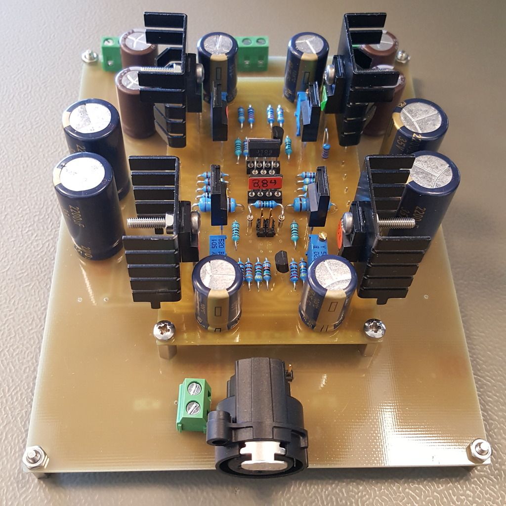
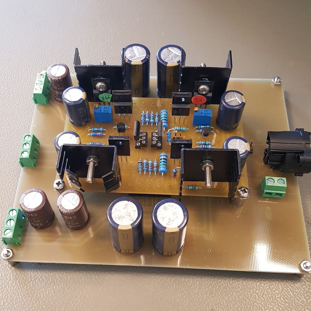
Bad pic of the balanced FE-board
I started DIY Audio almost 10 years ago with Aleph 30. My first Pass amplifer.
I didn't like the etching or drilling very much. A thought of CNC machine was the dream back then 🙂. Today I'm back with DIY gears and an even bigger AMP.
An externally hosted image should be here but it was not working when we last tested it.
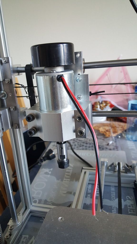
DIY CNC Milling/3D printer
An externally hosted image should be here but it was not working when we last tested it.
Bad pic of the balanced FE-board
Good luck.
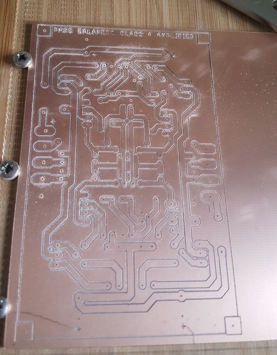
Give the routed board a really good scrub with dishwasher detergent and a toothbrush and finish under warm running water. You must get rid of all the loose copper fragments.
Did you buy or build the 3D router?
Is that another construction Thread?
Give the routed board a really good scrub with dishwasher detergent and a toothbrush and finish under warm running water. You must get rid of all the loose copper fragments.
Did you buy or build the 3D router?
Is that another construction Thread?
Thank you AndrewT! I did tin plated the board and polish with toothpaste. Unfortunately forgot to take a picture.
About 3D router it was my own and there is no thread. You can convert almost any printer to milling version. Here is the info:http://www.vellemanprojects.eu/downloads/0/user/usermanual_k8200_cnc_milling.pdf
About 3D router it was my own and there is no thread. You can convert almost any printer to milling version. Here is the info:http://www.vellemanprojects.eu/downloads/0/user/usermanual_k8200_cnc_milling.pdf
An externally hosted image should be here but it was not working when we last tested it.
It is 2 Sony Vfet pt2 front end. With R46 connected together like Walters X-Vfet amp. But I dont have the V-fets🙁
An externally hosted image should be here but it was not working when we last tested it.
Just use lateral fets if you can't get the vfets.
I can propose a circuit for those if necessary.
I can propose a circuit for those if necessary.

Bias at the moment 265mA/fet and the heatsink reaching 50ºC . The case is from HIFI2000 5U 500mm. I think I will need to go mono😀
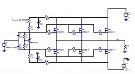
Lateral ouput
1) don't forget to add the feedback loop
2) Make sure you get the ADJUSTABLE version of LM385 (TL431 is not appropriate for lateral fets)
3) DC Offset is 500 Ohm trimpot
4) R1 is 5k Trimpot for Bias control
You can add as many laterals as you feel is necessary.
This should get you closer to the original Sony V2 sound with zero degeneration on ouput.
NOTE: Lateral pinout is GSD, not the usual GDS.
Attachments
Last edited:
I'm thinking of replacing lm385 with an led as voltage reference (maybe green).
Let us know before you proceed just in case I have made changes.
Let us know before you proceed just in case I have made changes.
No hurry! This amp took me many months to make boards and collecting parts. I knew V-fet FE wasn't suitable with IRFs. That is why I made this amp with exchangeable FE.
Thanks again.
Thanks again.
1........ (TL431 is not appropriate for lateral fets).......
why is that ?
Here is an adjustable shunt with 1.24V reference http://www.ti.com/lit/ds/symlink/lmv431.pdf
This one would work too.
This one would work too.
Vgs threshold of lateral fets is very low eg 0.5Vwhy is that ?
2,5 volt reference is too high for bias adjustment. You would then need to further voltage divide the output like you do with zener diode, in which case you may as well just use zener.
This one with 1.24V reference will certainly work though http://www.ti.com/lit/ds/symlink/lmv431.pdf
Last edited:
Was going to use adjustable lm385 which will also certainly work, but just realised these are adjustable band-gap devices not adjustable shunts.
I'm too lazy to learn/study the positives and negatives on adjustable band-gap devices vs shunts, so the adjustable LMV431 shunt with 1.24v reference is starting to seem more appealing to me.
I'm too lazy to learn/study the positives and negatives on adjustable band-gap devices vs shunts, so the adjustable LMV431 shunt with 1.24v reference is starting to seem more appealing to me.
BA-3B FE
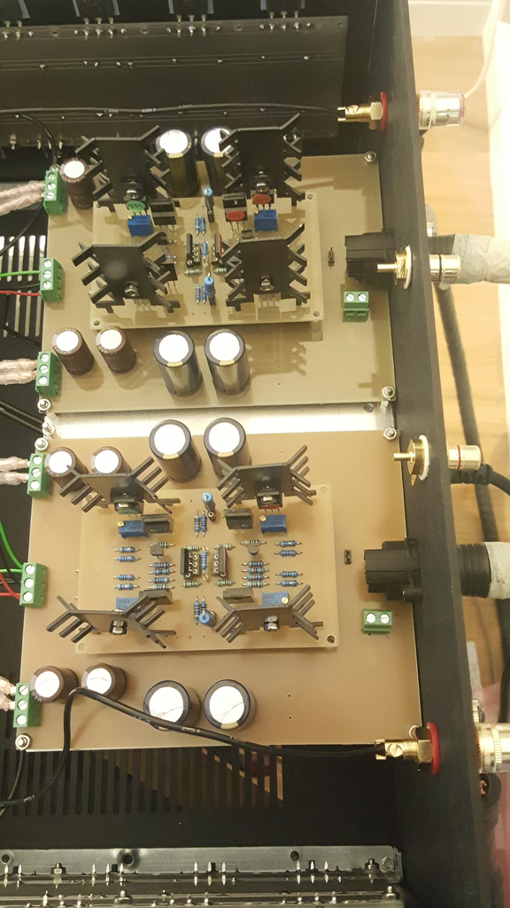
Update! BA-3B FE in place.
FE data:
10 years old 2SJ109BL and 2SK389BL (from Reichelt)
2SJ313 & 2sk2013 bias at 50mA (from NickMac)
OS data:
40 IRF FETs matched Ugs within 2mV@300mA (From Joachim Himmel Ebay)
1 ring transformer 2x18V 800VA supply both channel
12 Elcos 22000uF 40V
Chassis 5U 500mm HIFI2000.
First impressions. Everything gets HOT...HOT...HOT
Needs 24h burn-in before listening test.
Update! BA-3B FE in place.
FE data:
10 years old
2SJ109BL and 2SK389BL (from Reichelt)2SJ313 & 2sk2013 bias at 50mA (from NickMac)
OS data:
40 IRF FETs matched Ugs within 2mV@300mA (From Joachim Himmel Ebay)
1 ring transformer 2x18V 800VA supply both channel
12 Elcos 22000uF 40V
Chassis 5U 500mm HIFI2000.
First impressions. Everything gets HOT...HOT...HOT
Needs 24h burn-in before listening test.
- Status
- Not open for further replies.
- Home
- Amplifiers
- Pass Labs
- Building a balanced amplifier