The amp has worked and performed, for the most part, as desired; Until recently.
This amp is based on a stereo build version of the Sunn S100. I used Webers schematic with some basic changes. One of which is the bias circuit. Before I go through the trouble of editing the schematic to reflect the changes, I have a basic question related to the bias circuit, which is in it's 5th redesign. Here is the problem currently under analysis:
The output tubes are 6L6. Using the 1 Ohm cathode resistor measurement method, I can adjust the bias output to various values within the desired range all the way through to the grid resistors. However, the actual value at the 1 Ohm cathode resistors ends up being 2x the bias setting. How can that possibly be? With the output tubes removed the bias value all the way to the grid resistors reads the same as the bias output setting. However with the tubes in, the bias setting seems to double.
Thank you for any assistance you may have to offer,
Colorcat.
Questions unclear to me.
Just to be sure, bias or bias voltage is the voltage at the control grids. The current through the tubes we adjust bias for is idle current, or idle tube current. The bias power supply is the bias power supply voltage.
Do you have a common 1 ohm resistor, or separate 1 ohm resistors for each tube? And it sounds like you are measuring bias voltage at the 1 ohm resistors. But the bias voltage should be nowhere near the cathodes. if you are talking about the voltage dropped across the 1 ohm resistor, if it serves two tubes, then it will be twice what you expect.
What actual voltages do you get at any point in question? Telling me it doubles isn't informative. If you measure -50v and it goes to -100v, that is one thing, but if it goes from +2 to +4, that is totally different.
Schematic to be drawn.
I guess it's time to come up with the final schematic as there is another problem that needs to be solved after the bias issue.
So should the idle current have a different value then the bias current?
Enzo, I will retake the measurements today and post the data in a better defined format.
Thanks,
Colorcat.
Last edited:
Tube current is tube current, we measure it at idle to set the bias. Or at least that is one route.
Bias is a voltage we apply to the tube grid to control the current through the tube. We measure the current through the tube. This is done at idle. measuring tube current while the unit is amplifying a signal will totally obscure any bias readings.
I like to compare bias to setting the idle speed on your car motor. You have to do it at idle, you cannot set the idle speed while the car is driving around.
So you calculate the tube current you want, and measure the voltage across the tube - plate to cathode - multiply them to get the tube dissipation.
You set a target current. SO if I want 38 milliamps of tube current, then I adjust the bias voltage until I measure 38ma of current . With the 1 ohm cathode resistor, we measure voltage across it, and millivolts equals milliamps. That is why we use 1 ohms.
"Bias current" is idle current measured in the process of adjusting bias voltage on the grid.
This is what I've done
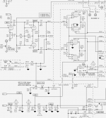
The following schematics indicate the changes in the bias circuit and the application of the design to my build. I've already gotten some clues after looking more closely at the original design application. The bias feed is different in the 6s100 implementation for one. Adding a second channel dropped the base load resistance of the bias output voltage. The 22k base resistance needs to be raised to something like 100k. There are notes regarding the setting of the bias on the Carvin schematic that I missed when implementing the circuit.
I still do not understand how I got 68 ma of tube current when the bias setting was -32 volts. (The bias voltage is separate from the tube current? But limits the current flowing in the tube?)
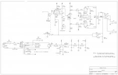
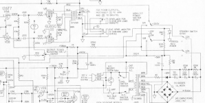
Schematics attached: original implementation, Carvin MTS 3200; Redesigned bias circuit as built; 6s100 output section using redesigned bias circuit.
The following schematics indicate the changes in the bias circuit and the application of the design to my build. I've already gotten some clues after looking more closely at the original design application. The bias feed is different in the 6s100 implementation for one. Adding a second channel dropped the base load resistance of the bias output voltage. The 22k base resistance needs to be raised to something like 100k. There are notes regarding the setting of the bias on the Carvin schematic that I missed when implementing the circuit.
I still do not understand how I got 68 ma of tube current when the bias setting was -32 volts. (The bias voltage is separate from the tube current? But limits the current flowing in the tube?)
Schematics attached: original implementation, Carvin MTS 3200; Redesigned bias circuit as built; 6s100 output section using redesigned bias circuit.
Attachments
Last edited:
Bias voltage controls the tube current, just like pressing down the car accelerator pedal controls the engine speed. The right end schematic shows a TRS jack for bias readings. Did you use that format? If so, if the tip and ring short together then two tubes are paralleled at their cathodes.
Are you consistently getting 68ma? Or just once? Do you have 450v or so on the plate supply? With the power tubes removed, measure the voltage on pin 5 of each socket. Turn the bias control. What range of voltage appears? For 6L6 and that level of B+, I'd tend to want about -60 down to maybe -45v. -50v being a rough average. -32v seems very low to me.
Are you consistently getting 68ma? Or just once? Do you have 450v or so on the plate supply? With the power tubes removed, measure the voltage on pin 5 of each socket. Turn the bias control. What range of voltage appears? For 6L6 and that level of B+, I'd tend to want about -60 down to maybe -45v. -50v being a rough average. -32v seems very low to me.
Happy Thanksgiving and...
I rebuilt the bias circuit, (changed out the fixed resistors from 22k to 47k), and now the bias ranges from -38 to -55 volts with the power tubes removed. I suspect the 22k variable resistor needs to be a 50k in order to get the range needed.
My implementation of the bias jack consists of a 1 Ohm cathode resistor to ground on each power tube. I measure the bias current across each resistor to get the tube current.
I won't be able to do much tomorrow as I'm the cook. I'll be back soon though. Thanks for your help,
Colorcat.
Progress but-
So the bias is now adjustable within the range I'm after. However, using two bias pots for 4 tubes leaves me with a rather large difference in settings for the pair of tubes in each channel. CH1 Va = 26 ma tube current at idle; CH1 Vb = 34 ma idle current.
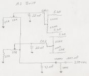
Using my existing bias supply design I'll add the balance pot like the Fender design as illustrated below. Does anyone see a problem with this?
Thanks for the assistance,
Colorcat.
So the bias is now adjustable within the range I'm after. However, using two bias pots for 4 tubes leaves me with a rather large difference in settings for the pair of tubes in each channel. CH1 Va = 26 ma tube current at idle; CH1 Vb = 34 ma idle current.
Using my existing bias supply design I'll add the balance pot like the Fender design as illustrated below. Does anyone see a problem with this?
Thanks for the assistance,
Colorcat.
Attachments
If you are concerned over all being alike, are you not buying matched sets of four to start with? Have you tested individual tubes so you can pair them with other tubes that more closely match them naturally? You might find the Ch2 tubes have similar mismatch but could pair with Ch1 to make two pairs of similar current.
You will note the Fender print shows the use of a center tapped pot, you have any of those?
But more fundamentally, you opened with the amp has been working as desired until recently. Why would we want to completely redesign the bias circuit now, when the old way worked until recently. Sounds more to me like something else in the amp failed. If the design were defective, the amp would always have sounded whatever bad way it sounds now. This is a guitar amp, not a precision NASA space probe.
Failure
To address the, "amp worked fine". That was a misstatement as I forgot why this new journey began. Each channel when operated separately worked fine. When I attempted to bring up both channels with a bias board using separate bias feeds for each tube, my problems began. I was never able to get the bias voltage up high enough for 4 separate feeds to operate. I believe it was due to the wrong value dropping resistor at the bias circuit AC input. After tinkering with different values I eventually just said, the heck with it and converted to a two channel bias, each channel feeding two power tubes each. Initially, the bias voltage level was too low, but changing out some resistors got that up to a functional level. That is where I left off yesterday. After tying the bias circuit depicted above into the grids, I found there to be a 10 ma separation between two of the output tubes in one channel. I don't need the bias to be exact but that is why I went with adjustable, so that I could get the setting fairly close without purchasing, yet another set of output tubes. This brings the story current to the point where I added the balancing pot from the Fender 75.
What happened next is: Today, as I brought the amp up, under the Variac, I observed the tube idle current slowly rise and then just kept on rising and ran away until the HV fuse burnt out. I also observed the watts consumption meter on the Variac indicate excessive power.
To check the circuit is functioning I removed the power tubes and set the outputs to -48 volts. When the tubes are put in the tube current still runs away. The last action taken was to remove the 33k resistor from the center tap of the balancing pot. I'm now going to check the circuit again to be sure the change was done as I intended.
Colorcat.
Success!
Well it's finally working, in stereo. There were a couple problems. One of the tubes was drawing more current than the others. I swapped it out and the bias settings all fell within 1.5 ma of each other. I may have been mis-adjusting the bias as my understanding of the bias voltage relationship to the actual bias current was incorrect. And finally: The balance pot from the Fender design is a 4 connection component; I learned after searching for more information last night. Apparently there is a 15k tap on it and the way I had it set up was not going to work. However, I still haven't gotten that to work either. For now, since the bias values are close enough and the amp sounds good, I'm going to move on to the next phase, which is to experiment with some preamp circuits.
Thanks for all the help Enzo,
colorcat.
- Status
- Not open for further replies.
- Home
- Live Sound
- Instruments and Amps
- Build Troubleshooting