Hi All,
I just built my Lampucera, I'm finding the Right Channel is outputing 6.0v and the Left Channel is outputting 5.5v. This was measured at the RCA connectors whilst playing a constant 35hz tone into the pre-amp. This voltage difference is enough to throw the imaging to the right. Are there any tips on balancing left and right output voltages? Initial thoughts was to tweak the Anode or Cathode Resistors on one set of the triodes which might drop the amplification to balance it? or is it a case of 6N6P's are all different amplifications on each triode?
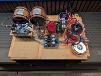
Picture for attention & thanks in advance
I just built my Lampucera, I'm finding the Right Channel is outputing 6.0v and the Left Channel is outputting 5.5v. This was measured at the RCA connectors whilst playing a constant 35hz tone into the pre-amp. This voltage difference is enough to throw the imaging to the right. Are there any tips on balancing left and right output voltages? Initial thoughts was to tweak the Anode or Cathode Resistors on one set of the triodes which might drop the amplification to balance it? or is it a case of 6N6P's are all different amplifications on each triode?
Picture for attention & thanks in advance
Attachments

Do you have an oscilloscope?I'm finding the Right Channel is outputing 6.0v and the Left Channel is outputting 5.5v.
No Oscilloscope, just a Fluke Multi-meter, probing the signal (+) and ground (-) on the RCA connectors. And setting a consistent measuring baseline, I'm using a 35hz test track on Tidal, which I think is pretty close to peak output voltage. You reckon an oscilloscope is the way to go to troubleshoot this? if so, what's a reasonable one to go for?
You might be able to figure out what's going on by swapping parts around between channels. A scope would be best though. New digital scopes have gotten pretty low-cost, but used analog scopes on ebay may be cheaper. Also, if you don't have a signal generator, then a scope that includes one can be handy.
For dacs, I usually recommend at least a 100MHz bandwidth, 2-channel scope. That's because dac for sure have RF in them, and 100MHz is pretty minimal for that. 200MHz would be better.
You could look on Amazon, for example, and see what they have with the above specifications. Probably a few hundred $$$ to for entry level for that sort of thing. But, if serious about the audio hobby a scope is virtually indispensable.
Siglent, Rigol and similar are sort of the standard brands. Some others are cheaper, but they are made cheaper.
Of course, to get the best out of one there is definitely a learning curve. However most have an AUTO button for beginners and or convenience.
Last edited:
I started this thread and then I disappeared halfway through. So I’m almost embarrassed to show my face. I intend to finish this thing, but reality and laziness have interfered. That out of the way, my great contribution is kind of obvious - please don’t be offended. Swapping parts (tube ?)and finding voltage points in the circuit that are parallel to each other for left and right might be helpful in localizing the problem. Hopefully the voltages are the same at some stage before diverging. A scope seems like a good thing to have generally, but it shouldn’t be necessary just to get the output voltages to match. The guy who sells Akitika has a very high quality signal generator (1khz 0-1.5V only, less than 2ppm distortion) for $90. https://www.akitika.com/akitikastore.html. You can also get a pretty good chinese signal generator on ebay (try fy6900) for $120.
Last edited:
Thank you all for the quick responses tonight, I'll do some more reading up and start looking down the power chain for the Anodes, thanks.
Kflex88, ive got a few of these boards (pre I2S SMD connections and same as yours) and have not experienced any issues.
May I suggest that you take some voltage reading directly from the DAC chip pins and post here?
Specifically:
1) between Analog GND (pin 21) and L- (pin 24), L+ (pin 23), R- (pin 19) and R+ (pin 20)
2) between L+ and L-
2) between R+ and R-
May I suggest that you take some voltage reading directly from the DAC chip pins and post here?
Specifically:
1) between Analog GND (pin 21) and L- (pin 24), L+ (pin 23), R- (pin 19) and R+ (pin 20)
2) between L+ and L-
2) between R+ and R-
Hi Taylorised et Al.,
This afternoon I was able to try something I suspected, swapping in a spare tube I had. I had dropped one of the pairs on the wooden kitchen floor the other day, I was surprised it didn't crack to be honest, and I kept it and thought nothing of it.
But having now swapped in the spare I had, I'm happy to report the issue has gone away now. Using my rudimentary testing, I measured 6.4volts output on both RCA's now. Glad that's sorted because it was quite distracting!
Hi kflex88,
Great news. Whilst it too early to now how it really sounds (clearly not enough hours have passed yet in a day to break my the capacitors in), are you happy with the result so far?
Great news. Whilst it too early to now how it really sounds (clearly not enough hours have passed yet in a day to break my the capacitors in), are you happy with the result so far?
Hi Taylorised,
Being a bit of a newbie in this game, without extensive listening experiences I speak from that limited perspective.
This is actually a second assembly (I'm preparing to put it into an enclosure), the first being in a testing build format. Going from the testing one to this one I have changed the wiring from 0.5mm gold plated Amtrans hook up wire for power and signal wiring, to 'Duelund DCA16GA 600Vdc tinned copper multistrand wire in Polycast sleeving' for power and 'Mundorf silver/gold wire, 0.5mm' for signal. I think there's been a slight improvement but hard to tell because it was great already.
I did try the Lampucera DAC board without the tube stage, that already brings a lot of detail to the table but adding the tube stage just makes the listening so comfortable whilst providing the same amount of detail.
For around a month between my first assembly and the second, I would listen to music with the Wiim Pro plus going straight into the pre-amp and power amp, I was very uninterested in what I was hearing, as I knew what it could sound like with this DAC in the chain, which is thick tight bass and great decay in notes and vocals.
Slightly off topic, also since the first assembly I've added the Puritan PSM156 power conditioner and Stack Audio's AUVA 100 speaker dampening feet into the system. And now bringing this DAC back into the system, I am in another world, the DAC just performs phenomenal now. Not sure how long this will last but I am so happy with my system right now, continuously entertained trying all my favourited tracks and albums.
Hello,
I built the Lampucera in the iiWi version and I am very satisfied with the sound. Thanks for the many forum entries, they helped me a lot.
Since I switched the opamp to tube, I get a short noise, a beep or a crackling, that sounds at the beginning of a new track. This noise is only, when the new track has a different bitrate or sample rate than the previous one, otherwise it is silent. The sound is about in the middle and not just on one channel.
I changed the power supply of the anodes and of the heating, changed the capacitors in the signal path and changed the cable routing. no success.
Does anyone have similar experiences with this Lampucera plan? I am grateful for recommendations.
Greetings from Austria
Franz
Attachments
Its because of the dropout that occurs when the dac and or the USB board switches clocks. If using a USB board, there should be a MUTE signal available that can be used to mute the dac analog outputs while the clock frequencies and or the sample rate are being switched over.This noise is only, when the new track has a different bitrate or sample rate than the previous one...
Thanks to Mogwai77 and to Markw4,
Ok, I found the explanation in the video. If I understand correctly, it’s a fact, Srba accepted it, and he doesn’t mind. But there’s no solution available.
I just ask without great hope: “Does anybody know a solution?”
The sound remains great, so I will have to accept.
The next part is to build a nice housing for my new dac and to watch if I can accept the disturbing sound persistently.
Furthermore open for help.
Kind regards
Franz
You didn't say if you are using a USB board for digital input to the dac (e.g I2SoverUSB or Amanero)? Finding the solution to your problem requires knowing more about your particular build.I just ask without great hope: “Does anybody know a solution?”
Also, can you post the output stage schematic?
The non expert solution I used was to lock the output bit rate on my streamer - Wiim Pro plus, since the board only takes 16 or 24 bit depth. No clicks or pops then, but I accept not all streamers has such a setting. On my Ian Canada streamer, you can set the output to be delayed for a certain amount of time (0.5 seconds recommended) for the the bit rate to be switched over, again I'm not sure if other streamers have that function. Good luck
You didn't say if you are using a USB board for digital input to the dac (e.g I2SoverUSB or Amanero)? Finding the solution to your problem requires knowing more about your particular build.
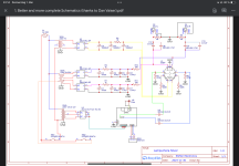
Also, can you post the output stage schematic?
Thanks for your willingness to help.
I don‘t use a USB board. My streamer is a bluesound node n130. I use it with optical spdif (the problem exists also with coax).
I put the schematic into the attachment, but I reduced the anode resistors from 15k to 1,5 k because I had to much gain with 15 k ( but also the noise problem). The input caps are russian pio 0,25 uf with silver mica 0,01 uf, the output caps are Russian pio 2 uf.
Differences are also in the heater psu (I used battery and alternative ac transformer). There was no difference with the problem, but the ac transformer made hum, so I will change the transformer with rectifier for dc).
Kind regards
Franz
Attachments
No MUTE output signal on that one.My streamer is a bluesound node n130.
What TOSLINK receiver is on your dac? Do you have a schematic or a pic of that board or module?
What happens if unplug the optical TOSLINK cable while music is playing? Do you get a pop?
What happens when you plug it back in? Pop noise?
- Home
- Source & Line
- Digital Line Level
- Build Thread: Lampucera DAC (iiWi version) - help needed