Got to the metal workshop and re-drilled and tapped my stripped circle jig. Finally got my driver hole routered and screw holes drilled. I should have used a drill bit as a transfer punch to mark the screw holes, had I been thinking rather than my pencil with its lead sticking out.

I used a chisel to cut slots for the driver frame:

It worked fairly well, I wished I had a pair of spring dividers as marking up the ply with the points of my vernier calipers in the recess was quite awkward:


Now we have a lot of work with the rasp as suggested by GM to give the driver some room to breath at the back!
In other news, the giant chamfer router bit arrived from Aliexpress, it's definitely a death trap! The bolt holding the bearing on has been drilled off-centre giving it a fun wobble
I used a chisel to cut slots for the driver frame:
It worked fairly well, I wished I had a pair of spring dividers as marking up the ply with the points of my vernier calipers in the recess was quite awkward:
Now we have a lot of work with the rasp as suggested by GM to give the driver some room to breath at the back!
In other news, the giant chamfer router bit arrived from Aliexpress, it's definitely a death trap! The bolt holding the bearing on has been drilled off-centre giving it a fun wobble
I borrowed a rasp from my local tool library to rasp out the back of the driver hole:

Test fit, hopefully the driver has enough breathing space:

Cut the acryllic ports to 6 inches:

My replacement giant router bit arrived. It's got enough width to chamfer the whole edge of the 18mm ply:
 Now all I have to do is glue the remaining panels, polish the cut face of the acryllic ports, stuff the speakers.
Test fit, hopefully the driver has enough breathing space:
Cut the acryllic ports to 6 inches:
My replacement giant router bit arrived. It's got enough width to chamfer the whole edge of the 18mm ply:

Great job. Well done.I borrowed a rasp from my local tool library to rasp out the back of the driver hole:
View attachment 1076611
Test fit, hopefully the driver has enough breathing space:
View attachment 1076612
Cut the acryllic ports to 6 inches:View attachment 1076615
My replacement giant router bit arrived. It's got enough width to chamfer the whole edge of the 18mm ply:View attachment 1076616Now all I have to do is glue the remaining panels, polish the cut face of the acryllic ports, stuff the speakers.
OK a whole year without progress...a lot has happened in my life and I'm now living in Cambridge UK away from my beloved Scotland. I changed career from being a software dev to a blue-ish collar worker in an engineering company. I'm now a test technician testing some really nice lab automation robotics and enjoying it a lot.
This past week I glued some cleats to allow me to be able to take the lid off in the future. I'll screw the lid into the battons and use clear silicone sealant as the 'glue'. I've done this before and it worked well.

Next I glued an extra layer of ply to reinforce the port.


And finally test fit the port, the fit is great.


Next to chamfer the edges. I'm contemplating painting all exposed plywood edges gloss white. To this end I've bought some Osmo water-based filler to fill the sanded endgrain.
It might be a bit of an effort to mask-off the non-edge parts but hopefully the effect might be cool.
I also bought some Osmo 3111 white tinted wax to finish the birch facegrain which should hopefully retain the light colouring.
This past week I glued some cleats to allow me to be able to take the lid off in the future. I'll screw the lid into the battons and use clear silicone sealant as the 'glue'. I've done this before and it worked well.
Next I glued an extra layer of ply to reinforce the port.
And finally test fit the port, the fit is great.
Next to chamfer the edges. I'm contemplating painting all exposed plywood edges gloss white. To this end I've bought some Osmo water-based filler to fill the sanded endgrain.
It might be a bit of an effort to mask-off the non-edge parts but hopefully the effect might be cool.
I also bought some Osmo 3111 white tinted wax to finish the birch facegrain which should hopefully retain the light colouring.
I'd like to canvas opinions on whether a good few coats of this sort of thing might make an acceptably smooth gloss finish on the plywood edges? I'm not aiming for piano perfection.

I'm thinking:
Sand plywood endgrain,
Apply filler,
Sand filler,
Apply filler,
Sand filler,
Vacuum,
Coat of rattle-can white nitrocellulose guitar paint,
Wet sand with some form of abrasive,
Coat of rattle-can white nitrocellulose guitar paint,
Wet sand,
Repeat repeat repeat...
I have good German Starke Matador sandpaper in grits up to 6000 and scotchbrite but I'm not sure what might be best between coats. I don't have access to a clean-room so I'll have to knock-off the encapsulated dust fibres.
Any thoughts very appreciated, I get overwhelmed by extremely conflicting advice everytime I have researched this topic.
You can as it's what replaced shellac, the traditional sealer, though won't give the same 'rich' quality finish of fine furniture if wanting to build it up to a properly sealed finish.
A small update, I have drilled the screw holes for the lid. I'm using m4 hex cap-head timber screws which now sit pretty flush.


I experimented with my 18mm deep aliexpress router bit and it works super well. It's sincerely nicely finished and cuts well. I know that this deep chamfer will mean my corner thickness will be ~12.8mm but I'll live with it. It's this one if anyone's interested: https://www.aliexpress.com/item/1005003752792808.html

And I glued-up the bottom of the box. I'm very thankful now to have access to sash clamps!

In other news, I was in a charity shop at the weekend and found this wonderful device I'd never encountered before, a proportional divider (Ecobra 3891, made in Germany) wow how bloody useful for speaker building, being able to divide a circle or line into however many parts you like! And £3.99, a bargain!
I've already graduated from rulers to dividers but this thing is the next level for me in reducing numerical maths (and my associated measuring errors) in the workshop.

I experimented with my 18mm deep aliexpress router bit and it works super well. It's sincerely nicely finished and cuts well. I know that this deep chamfer will mean my corner thickness will be ~12.8mm but I'll live with it. It's this one if anyone's interested: https://www.aliexpress.com/item/1005003752792808.html
And I glued-up the bottom of the box. I'm very thankful now to have access to sash clamps!
In other news, I was in a charity shop at the weekend and found this wonderful device I'd never encountered before, a proportional divider (Ecobra 3891, made in Germany) wow how bloody useful for speaker building, being able to divide a circle or line into however many parts you like! And £3.99, a bargain!
I've already graduated from rulers to dividers but this thing is the next level for me in reducing numerical maths (and my associated measuring errors) in the workshop.
Score ! That's several hundred folding less than new 🙂
https://greenandstone.com/product/ecobra-proportional-dividers-3891/
https://greenandstone.com/product/ecobra-proportional-dividers-3891/
Chamfering today. I did the easy bits before I get to the silghty trickier around-the-driver section.

I got over confident and did some passes a bit deeper than I should have and was rewarded with some tearout on the top of the speaker. Painfull. I'm going to try filler or maybe gluing birch splinters in there.

A pal offered to model-up a 3D printed template to help with the next bit of chamfering. The chamfer bit's bearing can ride over it to create the varying depth of chamfer around the driver like so. This will ensure concentricity between driver and chamfer.

This is the part I'll 3D print and stick to the side of the speaker with double-sided tape at the right height for the chamfer bearing to ride over it.

I got over confident and did some passes a bit deeper than I should have and was rewarded with some tearout on the top of the speaker. Painfull. I'm going to try filler or maybe gluing birch splinters in there.
A pal offered to model-up a 3D printed template to help with the next bit of chamfering. The chamfer bit's bearing can ride over it to create the varying depth of chamfer around the driver like so. This will ensure concentricity between driver and chamfer.
This is the part I'll 3D print and stick to the side of the speaker with double-sided tape at the right height for the chamfer bearing to ride over it.
Just stumbled upon this thread. Beautifull build, Ollyboyd! I'm curious to your progress and the result! No update?
@Paulus NL You're right it's high time for an update! Life is slow. I am now working as an R&D engineering technician at a lab automation place in Cambridge.
So...today I added the edging to the chamfers. I had an abortive attempt at this last week but I lacked a good blade to trim the edging. The edging is 0.5mm melamine with thermal glue backing. You 100% need a single-beveled blade to make the cut neat. I had a scalpel and very sharp chisel. The scalpel wouldn't stay flush with the edge due to it's twin bevel. The chisel had too-steep an angle on the blade and would cause the melamine to chip as the material was pared in twain.
So I found these 0.43mm single-bevelled utility blades which were super sharp and perfect for the job. https://prime-tooling.co.uk/product...led-one-side-2-notch-made-in-sheffield-2437-p .


The finished result. (ignore the fugly 3D printed test port)
.jpeg")
I was happy with the corners. The ply hasn't been sanded yet so I think it will smooth the close-up imperfections with the veneering glue slightly smearing onto the wood from the knife.

I'm experimenting with a 3D printed port. This was my test-fit. Needs to be about 0.6mm wider. I'll make the finished one out of a light aqua blue.
.jpeg")
.jpeg")
Thoughts on whether or not to cover these visible ply bits on the front?
.jpeg")
I have one more speaker to veneer, then sanding, oiling, 3d printing the feet.
So...today I added the edging to the chamfers. I had an abortive attempt at this last week but I lacked a good blade to trim the edging. The edging is 0.5mm melamine with thermal glue backing. You 100% need a single-beveled blade to make the cut neat. I had a scalpel and very sharp chisel. The scalpel wouldn't stay flush with the edge due to it's twin bevel. The chisel had too-steep an angle on the blade and would cause the melamine to chip as the material was pared in twain.
So I found these 0.43mm single-bevelled utility blades which were super sharp and perfect for the job. https://prime-tooling.co.uk/product...led-one-side-2-notch-made-in-sheffield-2437-p .
The finished result. (ignore the fugly 3D printed test port)
I was happy with the corners. The ply hasn't been sanded yet so I think it will smooth the close-up imperfections with the veneering glue slightly smearing onto the wood from the knife.
I'm experimenting with a 3D printed port. This was my test-fit. Needs to be about 0.6mm wider. I'll make the finished one out of a light aqua blue.
Thoughts on whether or not to cover these visible ply bits on the front?
I have one more speaker to veneer, then sanding, oiling, 3d printing the feet.
ollyboyd,
Nice work with the chamfering and shape around the driver.
Sorry if you've already mentioned this somewhere else - any particular reason for gluing on the melamine strips to the edges? Part of the overall aesthetic?
Nice work with the chamfering and shape around the driver.
Sorry if you've already mentioned this somewhere else - any particular reason for gluing on the melamine strips to the edges? Part of the overall aesthetic?
@zman01 I just wanted to try something a bit different other than having the large exposed ply edges. If I don't like the white in a couple of years, I can always peel them off.
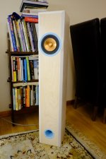
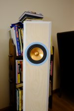
I finally finished! I'm super happy with how they sound and look. Soundstage is really superb, beaming is not a problem like I was worried.


Attachments


Last edited:
- Home
- Loudspeakers
- Full Range
- Build thread: Alpair 10.3 MLTL designed by Jim Griffin