G'day Guys,
I hereby start my build log of what will certainly be one of the ugliest projects around.
The old fridge clear out special (often quite tasty I might add): old experiments and obsolete projects thrown into the wok for a yummy creation suitable for listening in the basement while I fabricate more attractive things.
The goal of this project is to make a 50w per channel stereo amplifier with bluetooth for the least possible cost, time and effort.
First up may I introduce the chassis:
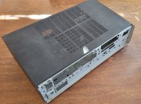
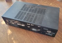
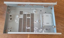
A salvaged chassis from a faulty old Yamaha RX-385 I got for free some time back:
Here's a photo of the original unit I found on google.

And after disassembly many years back and a little bit of hacking it now looks something like this:


It has some useful features:
1) It has a metal front panel unlike most salvaged av receiver chassis which saves me some bother fabricating one.
2) The back panel doesnt have too much crap on it so I can work around what is there rather than fabricate a new one.
3) It just happens to have mounting holes in place for the power transformer I found in my stash for the project.
4) It has some half decent venting in place for cooling.
5) Not too small, I can squeeze in what I need to.
6) It was free, a bit of drilling and it should be ready to go.
The budget for this project is $0 so I will be using what I can find in my stash
I will take the opportunity to experiment with using household paints on steel. Also to see if I can paint over this horrible thick black vinyl like stuff that comes on these things.
Just you wait and see the colour I plan to paint this thing. Hint:
I have a 4L bucket of an appropriate colour for painting a 3 year olds furniture.
Next up I will introduce some of the other ingredients in the stir fry.
I hereby start my build log of what will certainly be one of the ugliest projects around.
The old fridge clear out special (often quite tasty I might add): old experiments and obsolete projects thrown into the wok for a yummy creation suitable for listening in the basement while I fabricate more attractive things.
The goal of this project is to make a 50w per channel stereo amplifier with bluetooth for the least possible cost, time and effort.
First up may I introduce the chassis:
A salvaged chassis from a faulty old Yamaha RX-385 I got for free some time back:
Here's a photo of the original unit I found on google.
And after disassembly many years back and a little bit of hacking it now looks something like this:
It has some useful features:
1) It has a metal front panel unlike most salvaged av receiver chassis which saves me some bother fabricating one.
2) The back panel doesnt have too much crap on it so I can work around what is there rather than fabricate a new one.
3) It just happens to have mounting holes in place for the power transformer I found in my stash for the project.
4) It has some half decent venting in place for cooling.
5) Not too small, I can squeeze in what I need to.
6) It was free, a bit of drilling and it should be ready to go.
The budget for this project is $0 so I will be using what I can find in my stash
I will take the opportunity to experiment with using household paints on steel. Also to see if I can paint over this horrible thick black vinyl like stuff that comes on these things.
Just you wait and see the colour I plan to paint this thing. Hint:
I have a 4L bucket of an appropriate colour for painting a 3 year olds furniture.
Next up I will introduce some of the other ingredients in the stir fry.
Attachments


First up is the power transformer.
Salvaged from a faulty Sony STR-K1000P I purchased for $1 some time back.


200w according to the service manual.
It has some very convenient 25-0-25Vac high current taps as well as some 14-0-14Vac low current taps.
Very convenient. There is also some other ones I could use to make an auxilary supply to power the bluetooth module but I can't be bothered making another power supply for the project.
Next up is the main power supply:

Cobbled together from a Jaycar power supply kit PCB, It was one of the first linear power supplies I ever made back at the beginning of my DIY journey.
Not pretty or beefy but sufficient for my purpose here.
It may as well get used rather than make a new power supply.
Another Jaycar power supply. A jaycar KC5418 kitset I made many many years ago. The first power supply I ever made.
Nothing fancy just some LM317/337 regulators. Perfectly sufficient one again.


I will fix up that wonky capacitor during the build.
That's it for power supplies!
Salvaged from a faulty Sony STR-K1000P I purchased for $1 some time back.
200w according to the service manual.
It has some very convenient 25-0-25Vac high current taps as well as some 14-0-14Vac low current taps.
Very convenient. There is also some other ones I could use to make an auxilary supply to power the bluetooth module but I can't be bothered making another power supply for the project.
Next up is the main power supply:
Cobbled together from a Jaycar power supply kit PCB, It was one of the first linear power supplies I ever made back at the beginning of my DIY journey.
Not pretty or beefy but sufficient for my purpose here.
It may as well get used rather than make a new power supply.
Another Jaycar power supply. A jaycar KC5418 kitset I made many many years ago. The first power supply I ever made.
Nothing fancy just some LM317/337 regulators. Perfectly sufficient one again.
I will fix up that wonky capacitor during the build.
That's it for power supplies!
I like to keep things out of the landfill where I can. Plus chassis are expensive.
As are power transformers.
The difficulty with recycling chassis is always to work around the venting and stamped mounting features.
I've had to give up on one or two when they were too problematic.
As are power transformers.
The difficulty with recycling chassis is always to work around the venting and stamped mounting features.
I've had to give up on one or two when they were too problematic.
Next up is input and amplification:
Ali Express bluetooth board.

Nothing fancy, this module does have an antennae though which is the problem with many I have looked at as I like to enclose everything in a steel box so I would expect one without an antennae to at least have range issues.
https://www.aliexpress.com/item/100...order_list.order_list_main.191.42df1802LoNZ0k
The preamp will be my first attempt at a opamp based preamp.

I built this back in 2019 and was my first version of this. Nothing fancy at all just an NE5532 set to 1.5x gain followed by a volume pot and the other half of the opamp set to 1.5x again. Later versions were better but this one is just sitting around.
Last up is some Jaycar LM3876 boards I built back in 2018. My first chipamps. Once again, sitting around doing nothing so in they go.


Nothing amazing here but they are all sitting around gathering dust and I know they work.
Ali Express bluetooth board.
Nothing fancy, this module does have an antennae though which is the problem with many I have looked at as I like to enclose everything in a steel box so I would expect one without an antennae to at least have range issues.
https://www.aliexpress.com/item/100...order_list.order_list_main.191.42df1802LoNZ0k
The preamp will be my first attempt at a opamp based preamp.
I built this back in 2019 and was my first version of this. Nothing fancy at all just an NE5532 set to 1.5x gain followed by a volume pot and the other half of the opamp set to 1.5x again. Later versions were better but this one is just sitting around.
Last up is some Jaycar LM3876 boards I built back in 2018. My first chipamps. Once again, sitting around doing nothing so in they go.
Nothing amazing here but they are all sitting around gathering dust and I know they work.
G'day guys.
Things are progressing nicely on the build.
Preamp boards are tidied up and the stolen 100k resistors replaced.

Main side wiring is complete. Power transformer leads are dressed and the unused secondaries insulated with heatshrink and tucked away.


A funny mix of connectors being both spade a screw terminals but that's how it goes when you throw together whatever is in the fridge. You gotta make it taste good regardless.
I also completed the speaker protection. A Rod Eliot P33A board I had lying around:

And this board I've been meaning to try for a while:


I designed it to use salvaged output parts from faulty big brand amps I pick up when I see them for cheap.
-PCB mount speaker jacks
-Output relays.
Some of the top end amps use some nice gold plated jacks and Omron relays. Eg: Integras (which thankfully for me fault a lot). This one is the generic type of jacks and the bog standard panasonic relays one finds in the mid range models.
This build is a good chance to test it. If it works, then the next time a friend commissions a new amp build I can save them $20 each for some decent speaker jacks and $10 each on relays and use the nice salvaged parts in my stash.
Notice the rough as guts metal working.
Approximately zero care has been taken on this build. Drill some holes in about the right spot then file things out till it fits!
Progress will now be glacial for a while as we have a new member of the family this week. Hobby time will be curtailed in exchange for sleep. I also won't be allowed to solder/build at my computer desk in the bed room anymore. Baby has commandeered the use of the space and solder fumes are no-no in the room the baby sleeps in, so says she who must be obeyed.
As I type, young Phoebe sleeps on my chest since she refuses to be put down and mama gets some precious sleep behind me. Brings me back a few years to the first one....
One day I get to teach the girls to solder!
Things are progressing nicely on the build.
Preamp boards are tidied up and the stolen 100k resistors replaced.
Main side wiring is complete. Power transformer leads are dressed and the unused secondaries insulated with heatshrink and tucked away.
A funny mix of connectors being both spade a screw terminals but that's how it goes when you throw together whatever is in the fridge. You gotta make it taste good regardless.
I also completed the speaker protection. A Rod Eliot P33A board I had lying around:
And this board I've been meaning to try for a while:
I designed it to use salvaged output parts from faulty big brand amps I pick up when I see them for cheap.
-PCB mount speaker jacks
-Output relays.
Some of the top end amps use some nice gold plated jacks and Omron relays. Eg: Integras (which thankfully for me fault a lot). This one is the generic type of jacks and the bog standard panasonic relays one finds in the mid range models.
This build is a good chance to test it. If it works, then the next time a friend commissions a new amp build I can save them $20 each for some decent speaker jacks and $10 each on relays and use the nice salvaged parts in my stash.
Notice the rough as guts metal working.
Approximately zero care has been taken on this build. Drill some holes in about the right spot then file things out till it fits!
Progress will now be glacial for a while as we have a new member of the family this week. Hobby time will be curtailed in exchange for sleep. I also won't be allowed to solder/build at my computer desk in the bed room anymore. Baby has commandeered the use of the space and solder fumes are no-no in the room the baby sleeps in, so says she who must be obeyed.
As I type, young Phoebe sleeps on my chest since she refuses to be put down and mama gets some precious sleep behind me. Brings me back a few years to the first one....
One day I get to teach the girls to solder!
G'day Guys,
As expected, build time has been severely limited and progress slow however the build is 'complete' for testing.
I can now proudly reveal the disgusting yellow paint I have used for this build.
I can't help but giggle each time I look at it. It is horrid!
It was an interesting experiment in using domestic primer and paint intended for wood.
Also I didn't bother removing the old paint on the chassis first.
I took almost no care whatsoever in the application of the paint so there is plenty of drips, runs and brush strokes.
Adhesion was decent. Masking of the old paint was decent. Masking of my marker marks from the sloppy metal work was less good.
With care taken in the application a decent finish could probably be obtained but I don't think it is worth the effort compared to go quality spray paint like my favourite Rustoleum hammer black or antique pewter.


You may notice some slight hacking of one of the fins on the salvaged heatsink. In my sloppy haste my tapping of the M3 hole for the right channel was **** poor. It went unnoticed during test fitting but as soon as I attempted to torque up the bolt I found the problem.
Rather than waste any precious baby not yelling at me time on drilling and tapping a new hole, moving the amp board accordingly, drilling more holes for the standoffs I took a much lazier approach. I grabbed my least favourite wire cutters and hacked a section of heatsink fin out of the way so that I could simply attach a nut onto the bolt!
Over the next couple of days I will start runnings some tests before doing a final tidy of the wiring before commisioning the new amp with some wood working and painting on a TV cabinet for SWMBO.
As expected, build time has been severely limited and progress slow however the build is 'complete' for testing.
I can now proudly reveal the disgusting yellow paint I have used for this build.
I can't help but giggle each time I look at it. It is horrid!
It was an interesting experiment in using domestic primer and paint intended for wood.
Also I didn't bother removing the old paint on the chassis first.
I took almost no care whatsoever in the application of the paint so there is plenty of drips, runs and brush strokes.
Adhesion was decent. Masking of the old paint was decent. Masking of my marker marks from the sloppy metal work was less good.
With care taken in the application a decent finish could probably be obtained but I don't think it is worth the effort compared to go quality spray paint like my favourite Rustoleum hammer black or antique pewter.
You may notice some slight hacking of one of the fins on the salvaged heatsink. In my sloppy haste my tapping of the M3 hole for the right channel was **** poor. It went unnoticed during test fitting but as soon as I attempted to torque up the bolt I found the problem.
Rather than waste any precious baby not yelling at me time on drilling and tapping a new hole, moving the amp board accordingly, drilling more holes for the standoffs I took a much lazier approach. I grabbed my least favourite wire cutters and hacked a section of heatsink fin out of the way so that I could simply attach a nut onto the bolt!
Over the next couple of days I will start runnings some tests before doing a final tidy of the wiring before commisioning the new amp with some wood working and painting on a TV cabinet for SWMBO.
It is complete!
One ugly as sin amplifier made out of old projects and scraps.
No problems with testing. One advantage of not making anything new is that I know all the bits work.
Of course the speaker protection board was new but I have made a bunch of them now so its nothing new.
The power transformer is rather noisy but that's not a big deal.
The wiring is not even remotely up to my usual standard but its ok. Its just for the basement while wood/metal working.


All in all a great little project with some good experiments including.
The salvaged speaker jack/relay board worked a treat. I will definitely use it again the future.
The paint experiment went about as I expected but it was good to prove the hypothesis.
Adios until the next build.
One ugly as sin amplifier made out of old projects and scraps.
No problems with testing. One advantage of not making anything new is that I know all the bits work.
Of course the speaker protection board was new but I have made a bunch of them now so its nothing new.
The power transformer is rather noisy but that's not a big deal.
The wiring is not even remotely up to my usual standard but its ok. Its just for the basement while wood/metal working.
All in all a great little project with some good experiments including.
The salvaged speaker jack/relay board worked a treat. I will definitely use it again the future.
The paint experiment went about as I expected but it was good to prove the hypothesis.
Adios until the next build.
Interesting build.🙂
I'm curious as to why a preamp was needed. Do the chip amp boards have a low input sensitivity?
I'm curious as to why a preamp was needed. Do the chip amp boards have a low input sensitivity?
Love the build and how you're shoehorning it in the midst of new parenting. Mine have now both left for college and I find there will be much more time for building in the not too distant future. My build (which I noted in the chip amp photo gallery) is just an amp, no driver stage/preamplification. I never tried the LM3886 board with just an input pot. Might be OK as all of my sources can certainly drive it to more than sufficient levels via a no-gain preamp (a 3S4 tube line stage configures as a follower). Mine also sits in the basement workbench area...
Force of habit. I like to have a preamp to make sure the volume pot is nicely buffered. The preamp is only 2x gain iirc.Interesting build.🙂
I'm curious as to why a preamp was needed. Do the chip amp boards have a low input sensitivity?
Mostly because I had the boards sitting around after experimenting with a few versions of this design.
@Sadface
What amplifier do you use - schematic?

The old Silicon Chip magazine design. Nothing fancy. Arguably not a top notch design but it works.
I got a couple of these kits on clearance a while back. My first chipamp kits.
Here is the article.
Attachments
The Lm3886 probably better for most as it can drive 4 ohm loads whereas the lm3876 is not entirely happy with 4 ohm.
Both can sound pretty darn good with the right implementation.
You can actually pay several thousand dollars for some lm3886 chips in a fancy box with a fancy name.
Both can sound pretty darn good with the right implementation.
You can actually pay several thousand dollars for some lm3886 chips in a fancy box with a fancy name.
- Home
- Amplifiers
- Chip Amps
- Build log: The Stir Fry - A throw together for the basement