Hello everybody, I am a new user of this forum, I have been reading for long time and now I decided to register and write some questions to you all.
Long time ago I bought a small "laney" stage monitor that had turned out to be a fake one, not a laney at all, nor the amplifier nor the cone.
After few days of usage the amplifier broke, I don't know very well the reason.
I opened it and saw that was a stk4048V amplifier.
Today arrived my new STK4048V chip from U.K. and I started to wonder if, using some pieces from the old broken pcb, I could make a not-lasting-only-two-days amplifier.
I have the transformer (very heavy) I have the new chips and I can test all the components of the old PCB. Maybe I need to change the cone, but I do not know how because I do not have another amplifier.
And here come your help, if someone wants to spend few minutes or few hours to help me I need to:
- Know if the old scheme is a valid and working one or, in case, change it.
- Know if there is something I can do to improve the scheme.
- Know how to properly test if the old components are good or burned.
- Know how to test the old cone
- If the cone is gone (and maybe the cone was not compatible with the amplifier) know how to choose a new cone.
I have a very beautiful wood case, like a real stage monitor, with the grille, space for a tweeter and a woofer etc.
If someone knows the stk4048V and wants to help me, please answer to this message. In a few days (because I have two university exams) I will post the circuit scheme.
I do have:
- low tension solder station
- digital multimeter
I do not have:
- oscilloscope
- spectrumscope
Have a nice day, Gianmarco
p.s. sorry if I made any mistake with the language, I am Italian.
If the unit is "fake" then I think the first think to confirm is that the power supply voltages to the STK are correct and not to high.
I would recommend using a "bulb tester" for initially powering and testing so as to avaoid damage to the new IC's.
I would recommend using a "bulb tester" for initially powering and testing so as to avaoid damage to the new IC's.
Can you please explain what a "bulb tester" is? just putting a light blub (220V ?) in the out of the IC?
Tomorrow I will work to write the circuit, then I will post what the actual values of voltage are.
Tomorrow I will work to write the circuit, then I will post what the actual values of voltage are.
Its just a mains filament 100watt bulb placed in series with the mains supply to limit current in the event of a fault.
You'll find many references to it on the forums.
You'll find many references to it on the forums.
The bulb works on a different principle. When the filament is cold it has a low resistance. Measure one and see 🙂 If the current drawn by the amp is low, the filament stays at a relatively low resistance and drops only a little voltage.The bulb isn't lit. If there is a fault and excess current is drawn the resistance rises rapidly, the bulb lights and the current is reduced saving damage.
cool!
I have the old IC, do you think is better to use that one instead of the new one? I don't now if is the IC or something else that is causing problems.
Perhaps I'm not sure that the cone is working, and if it is, I am worried I could burn it.
Do the bulbs save the speaker also?
I have the old IC, do you think is better to use that one instead of the new one? I don't now if is the IC or something else that is causing problems.
Perhaps I'm not sure that the cone is working, and if it is, I am worried I could burn it.
Do the bulbs save the speaker also?
The bulb would probably give you time to save the speaker but you should have confirmed that there is no DC present before even thinking about connecting the speaker.
You need to be methodical. Check the supplies and, assuming it runs off "split" or dual rails (as most amps do) you then check that the speaker output is at zero volts DC.
The old IC may or may not be faulty. Only careful voltage tests will tell.
You need to be methodical. Check the supplies and, assuming it runs off "split" or dual rails (as most amps do) you then check that the speaker output is at zero volts DC.
The old IC may or may not be faulty. Only careful voltage tests will tell.
ok tomorrow I will re-connect the old IC, put the light bulb in series to the main supply, test if is there any DC voltage. If the DC is zero then I put the speaker and take some voltage in the circuit.
Is there any method with the multimeter to check if the speaker is dead or not?
Is there any method with the multimeter to check if the speaker is dead or not?
You can measure the resistance on your meter. It will be around 4 to 10 ohms. Also connecting a 1.5 volt battery across the speaker will cause the cone to move in or out depending on polarity. Assuming its a large speaker then the cone should move freely and easily. Any rubbing or "scratchiness" indicates a problem.
Post the schematic and a couple pictures of the "Laney".
Front/back panel
Closeup showing the back panel power/voltage/"made in"/etc. inscriptions.
Inside showing:
Preamp PCB
Power amp PCB
Power transformer
Loudspeaker.
I don't think it's a "fake", but maybe a cheap modern one made in China or something.
Front/back panel
Closeup showing the back panel power/voltage/"made in"/etc. inscriptions.
Inside showing:
Preamp PCB
Power amp PCB
Power transformer
Loudspeaker.
I don't think it's a "fake", but maybe a cheap modern one made in China or something.
I am sorry I've been away for few days and I tried some mesurements only this night.
I finished to write down the schematic, it's a first scheme, I will try to correct it and make it more linear.
Here is the picture:
First of all I hope the picture is large enough to read all the values and to see all the connections. The rectangular shape on top of the schematic represent the STK4048V, pin 1 on the right.
Blue/Red are the main connectors for AC coming out of the transformer.
+/- on the left are the connection to the speaker
+/- on the right is the input (passing through a pot)
A is only a direct connection between the two part of the circuit.
8R2 resistors are unknown watt
22R resistors are 5W
diodes are P600K (first time I know they even exist)
inductor is a 47 turns of maybe 0.5mm wire with a radius of about a pencil.
What do you think about this circuit?
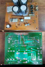
This is the PCB, top and bottom. Actually the Laney is completely de-assembled.
Then I tested the cone both with a tester and a 1,5V battery.
The results are misguiding.
I Obtain a 4 ohms resistance (the cone is 8 ohm), and I can se the cone moving, connecting the battery. BUT if I push the cone with the hands it seems not to be perfectly free to run, maybe I push too much and it will never reach that kind of movements.
What do you think?
Last but not least, I tried the transformer.
connected ALONE to the main 220V, it give at the secondary:
~->0 49,6V (AC)
~->~ 99,2 (AC)
Waiting for your answers
I finished to write down the schematic, it's a first scheme, I will try to correct it and make it more linear.
Here is the picture:
An externally hosted image should be here but it was not working when we last tested it.
First of all I hope the picture is large enough to read all the values and to see all the connections. The rectangular shape on top of the schematic represent the STK4048V, pin 1 on the right.
Blue/Red are the main connectors for AC coming out of the transformer.
+/- on the left are the connection to the speaker
+/- on the right is the input (passing through a pot)
A is only a direct connection between the two part of the circuit.
8R2 resistors are unknown watt
22R resistors are 5W
diodes are P600K (first time I know they even exist)
inductor is a 47 turns of maybe 0.5mm wire with a radius of about a pencil.
What do you think about this circuit?
This is the PCB, top and bottom. Actually the Laney is completely de-assembled.
An externally hosted image should be here but it was not working when we last tested it.
An externally hosted image should be here but it was not working when we last tested it.
Then I tested the cone both with a tester and a 1,5V battery.
The results are misguiding.
I Obtain a 4 ohms resistance (the cone is 8 ohm), and I can se the cone moving, connecting the battery. BUT if I push the cone with the hands it seems not to be perfectly free to run, maybe I push too much and it will never reach that kind of movements.
What do you think?
An externally hosted image should be here but it was not working when we last tested it.
Last but not least, I tried the transformer.
connected ALONE to the main 220V, it give at the secondary:
~->0 49,6V (AC)
~->~ 99,2 (AC)
Waiting for your answers
1) join the multimeter tips, I'd be very surprised if it shows "0".
It will probably show something around 1 ohm, the wire/connectors/etc. internal resistance.
Substract it from your 4.1 ohms reading and you'll have the actual Voice Coil speaker resistance.
Anyway it's already pointing to a 4 ohms speaker, not an 8 ohms one by any means.
The speaker is a cheap generic Eminence, not bad for guitar; vor voice use you'll need some tweeter, a Piezo is easy, cheap, and fine in this use.
2) that PCB is crap, not worth repairing.
Terrible design. Long thin high current tracks, not surprising they overheat and die under high power demands.
Get any Power amp which is happy with your transformer.
Post a picture and lamination height/width/stacking. "Very large" is not useful data.
Draw a transformer diagram showing colours and where you measure what.
50VAC+50VAC secondaries are way too much for a 60 to 100W amp.
3) just curious, where are you writing from?
Suggested solutions depend *a lot* on where you live and what you have access to.
What will you use this for?
1) do you think I need to change cone? In the back his nominal impedance is 8ohm, with the subtraction you told me I have less than 4ohm. Is the cone gone?
2) PCB, do you think I have to re-project a new one? If I put a layer of tin on top of each track, so they become thicker, can be a solution?
In a few I will post some other detail about the transformer
3) I am writing from Italy, where the main voltage is 220V@50Hz
I will use it on a stage, live with my piano and singing
Maybe.1) do you think I need to change cone? In the back his nominal impedance is 8ohm, with the subtraction you told me I have less than 4ohm. Is the cone gone?
Or maybe it was reconed.
I think your fake Laney was made by somebody with different scraps and parts he had around.
To begin with, I very much doubt British (or Chinese) Laney uses an American Eminence speaker, so .....
Try the speaker with another amplifier, even aTV or a radio or something.
If it works ... it worke.
But in that case it's 4 ohms .
Well, that's no Laney PCB for sure but something bought at a shop for peanuts or pulled from another amplifier.2) PCB, do you think I have to re-project a new one? If I put a layer of tin on top of each track, so they become thicker, can be a solution?
In a few I will post some other detail about the transformer
It's not homemade because it has soldermask.
Which complicates things a lot to add tin.
It's much better to add flying wires from end to and.
I show you an example with the +/- rails and the speaker out, but you must detect other high current carrying long thin tracks and do the same.
But I think the best is to buy a new 100W PCB (or a kit and build it) and power it from the "Laney", not using the STK.
The Power supply section is good.
Anyway, you will need to build a preamp for your piano and voice.
FORZA AZZURRI !!!! 😛3) I am writing from Italy,
Attachments
Thank you all for the advices, today and the next few days I am on duty in event of the election days here in italy, so I can't spend much time on the amp.
@JMFahey: I already have an audio service, many mixer and other active speakers, so no need for the preamp
@JMFahey: I already have an audio service, many mixer and other active speakers, so no need for the preamp
I am writing after a long 2 hour of internet surfing, datasheet and soldering.
I discovered that the scheme is the "basic" scheme that is presented in the datasheet of the stk4048V, an is exaxt the same of mine, except for two 10uF electrolitic capacitors (100V) between +_vcc and 0 and a 1uF capacitor between pin 10 and 7.
The rest is identical.
I tried to improve the pcb, with some extra wires, scraping off the green thing over the tracks and tinning all of them (or where it seems to be too small track).
Here is the result:
PCB
the transformer:
TRANSFORMER
the schematic, updated.
SCHEME
in the red dotted area there are the 3 condenser missing from the original scheme.
The resistors at pins 13,16,17,18 are 0,22 ohms. I don't know if the one in my pcb, connected to pin 13 is correct. is a 22R J L6, RIY7.
Any comment?
22r "should" mean 22 ohms, but in ceramic resistors it probably means 0.22 ohms .
Measure them just to be sure.
We don't need precision here, just to distinguish between 22 and 0.22 .
They probably are emitter ballast resistors.
The amp can work without those 3 capacitors, but if possible I would add them to get closer to the datasheet, which we can trust.
And yes, that "Laney" is an Italian made fake, probably homemade to be sold at EBay or similar for a better price.
The speaker is American , the PCB is quite poor and probably was part of a kit and the transformer is Italian, so ...
Anyway, you can build a powered monitor with it.
Only thing that worries me is that 43+43V is way too much for a 60/100W amplifier, it means +/- 60V rails.
I would feel comfortable with around +/- 40V DC.
Don't you have another spare transformer?
Something like 25/25 to 30/30VAC.
Even if the STK stands that voltage, it will need a lot of heatsinking , it will put out way over 150W into 4 ohms, and that speaker barely stands 50/60W at most.
I tried to measure the resistor, but seems to be broken. No values are shown in the display. Mumble, what can be happened?
What are "emitter ballast" resistors?
I don't have a 10uF 100V capacitors, but maybe I have a 1uF to add between pin 7 and 10
I don't think I have a smaller transformer, by the way, the datasheet tell about a +-60 as suggested value, and I have a big (about 20cm x 7cm x7cm) heatsink
What are "emitter ballast" resistors?
I don't have a 10uF 100V capacitors, but maybe I have a 1uF to add between pin 7 and 10
I don't think I have a smaller transformer, by the way, the datasheet tell about a +-60 as suggested value, and I have a big (about 20cm x 7cm x7cm) heatsink
- Status
- Not open for further replies.
- Home
- Amplifiers
- Chip Amps
- Build an active stage monitor - STK4048V