Hi Dick,
I think maybe you need to figure out some tricks with the tuning cap.
Is there such a thing as a capacitance multiplier for an air cap? If the impedance can be brought down then you can use larger components for the rest and not worry about loading so much.
I'm thinking about the HP TT analyzer and their variable cap method.
Cheers,
In looking at the manual's Block Diagram (Fig 4-1) and schematic.....the straight-thru distortion from input to output while in the voltmeter function/mode is pretty high. I would look at the crude meter circuit hanging off the output fist, then the input buffer amp (Impedance Converter) to reduce the 2H.
Thx-RNMarsh
Hi Rick,
Why don't you borrow some of the circuitry from the 339A. You have two.
You can wire from one unit to the other. This would save you from having to build.
Saving me time in building? I like that. But it might be just a mod or two to clean up and make useable the 334A. Worth a look and a run thru. I have 3 each 339A now. Need one to try your idea with?
I would like to do something for the readers here that they could use and easily/cheaply copy for their use.
Thx-RNMarsh
I would like to do something for the readers here that they could use and easily/cheaply copy for their use.
Thx-RNMarsh
Saving me time in building? I like that. But it might be just a mod or two to clean up and make useable the 334A. Worth a look and a run thru. I have 3 each 339A now. Need one to try your idea with?
I would like to do something for the readers here that they could use and easily/cheaply copy for their use.
Thx-RNMarsh
This is just for testing concepts. If you think the meter amp is at fault then borrow the one in the 339a. Once things are proven out then you can work something else out.
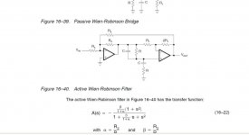
I quickly made an LTspice sim of the Wien-Robinson notch filter; I'd never heard of this filter until today, when a I got a book called "Circuit Design: Know it all," from Newnes Press. Turns out the circuit is very similar to one I designed myself when i was trying to get the HP334 to work better. Sadly, this circuit, like nearly any for a Wien notch filter, still has a diff amp for the post-filter amp, so common-mode issues will be there....
Here are the design steps for this filter (I chose the circuit values to be in the mid-range of impedances, but the tuning Rs (R6, 7) and Cs (C1, 2) are roughly those found in the 334 at 1kHz):
1. Pick f, R, and C for tuning using f=1/2Pi*RC.
2. Pick a filter Q -- I ended up with a Q of 3, which gives a 2nd H. attenuation of about 0.25dB.
3. Pick a throughput gain, A -- I chose unity. The 334 filter system attenuates by a factor of 3, which is not good from a s/n point of view, so unity gain should improve that by about 10dB, but will mess up the output scale on the front. To keep things as they are in the 334, a gain of -10dB (0.3162) could be used, but I haven't looked at what that does to parts values....
4. Calculate alpha = 3Q–1
5. Calculate Beta = A*3Q
6. Define R2
7. Calculate R1 = R2/Beta
8. Calculate R3 = R2/alpha
The 334's auto-tune adjusts R6 and R7 to tune for phase, so that should still work OK in a 334 mod. Varying either R4 or R5 adjusts the amplitude balance, and the stock system also should be usable in a 334 mod, though auto-tune signal polarity will need to be checked.
Hi Dick,
Is U1 place properly? The output slams against the rail in transient analysis.
Saving me time in building? I like that. But it might be just a mod or two to clean up and make useable the 334A. Worth a look and a run thru. I have 3 each 339A now. Need one to try your idea with?
I would like to do something for the readers here that they could use and easily/cheaply copy for their use.
Thx-RNMarsh
Richard-
You can use the Shibasoku to find where the distortions are coming from. Hang a 1:1 probe on its input and look at the distortion at each stage. With the analysis its pretty easy to see who is contributing the most.
A trick I discovered- I'm using my phone as a spectrum analyzer on the output of the 725. You need to sacrifice a headphone cable that has the mike connections to access the mike input on the phone (android) and there are a number of free/cheap fft programs that are very adequate to looking at the spectrum after its been preprocessed by the analyzer. Much quicker and much less of a hassle to deal with.
The phone ---- I have an early Touch model and loaded it with T&M stuff.... even FFT and many cheap downloadable software. RTA, THD, Freq, EQ, speaker/room checks -- very cool. I plug a small electret mic into it and have a SPL/RTA meter. All sorts of nice stuff available.... great for on-location spot checks and trouble shooting etc. Using it on the 725 I hadn't thought of. nice idea. Thx-RM
@davada -- I was in a hurry, David, and didn't run a transient analysis -- so anything could be going on -- but just looking at the various gains in the schematic, I can't see any reason that would happen. At null, as you know, strange things go on, so that may be an artifact of the test frequency....
@davada -- I was in a hurry, David, and didn't run a transient analysis -- so anything could be going on -- but just looking at the various gains in the schematic, I can't see any reason that would happen. At null, as you know, strange things go on, so that may be an artifact of the test frequency....
I ran it at 2kHz.
Indeed. Easier to wire the power that way.
Sim distortion looks okay.
This circuit doesn't have the positive feedback that you original circuit had.
It might perform better
Sim distortion looks okay.
This circuit doesn't have the positive feedback that you original circuit had.
It might perform better
Attachments
Last edited:
Hi Dick,
The differential voltage at the input of U2 is about 20uVpp with a 1Vpp input to the filter. This shouldn't present a common mode problem.
The differential voltage at the input of U2 is about 20uVpp with a 1Vpp input to the filter. This shouldn't present a common mode problem.
RE my post #138 in this thread -- I made the mistake of reversing the inputs of U1 -- Thanks David for catching that.
Here are the correct .asc and .jpg files for the Wien-Robinson notch filter. The values in this schematic yield Q = 3, which results in about 0.19dB of 2nd H. attenuation -- a Q of 2.5 gives about 0.32dB attenuation. Sorry for the error.
Here are the correct .asc and .jpg files for the Wien-Robinson notch filter. The values in this schematic yield Q = 3, which results in about 0.19dB of 2nd H. attenuation -- a Q of 2.5 gives about 0.32dB attenuation. Sorry for the error.
Attachments
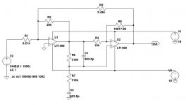
I got it working but the opamps seem to oscillate in the simulation. I had to put a 10pF 100 Ohm series network in parallel with the 18K resistors to get it to stop oscillating.
I got it working but the opamps seem to oscillate in the simulation. I had to put a 10pF 100 Ohm series network in parallel with the 18K resistors to get it to stop oscillating.
The 1468's need that to null their input capacitance. They are fine with 1k FB R or so but anything higher....
Cheers,
I would probably build with OPA1641s.
It's oscillating with the opa1641's
I checked out the 334A a little for its potential suitablity as a variable notch filter..... replaced a few electrolytics with back-to-back electro and bipolar types for lower 2H. Then I recal'ed the input and meter driver/output circuits.... if you use an ADC with FFT, you do not have to adjust the bias/thd pots inside for thier ref voltage number (which assures it meets specs)... just adjust for lowest distortion. I picked up 5dB from that alone.
I monitored the osc input at the 334A input port with a stock QA400. The 2H and 3H indicated about -120dB each. Then, thru the 334A output port (monitor out). Instead of remaining relatively equal in harmonic amplitute relationship, I measured it again and the 2H was 17dB higher. 3H was same.
So, either the 334A adds some 2H or the QA400 adds some... or both...the level is very low going into the QA400.
next... to check which contributes the most to the 2H increase and how much. -RNM
Attachments
Last edited:
dropped the THD a lot by simple change---
A quick look at the schematic says -from experience- hanging a meter/diode directly on the line is asking for trouble. Needs a buffer from the signal line.
I nulled a 1KHz signal on the front panel meter and at residual monitor output of the 334A via an QA400. I took a residual reading.
Then, I removed a lead wire to the meter movement. All the harmonics dropped a lot (see attachment). I repaced the meter with a R = 1K and got the same higher level as when the meter is in place. Possibly, the amp cannot drive the 1K load without increased distortion. Or what. need to check further for no gain change. Otherwise ->
I will either place a meter disconnect switch somewhere or add a meter buffer... Then, I can try adjusting the bias on the front end amp circuit as well and see if i can pickup a few more dB's.
Thx-RNMarsh
Last edited:
- Status
- Not open for further replies.
- Home
- Design & Build
- Equipment & Tools
- Build -- Active Twin-T notch filter for distortion analysis