Hi guys.
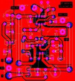
I'm working on a little buffer Preamp to sit in front of my chip amp (lm4780 parallel setup). This is one channel.
The values used are not necessary the values i will use as i haven't made a prototype yet. I'm a newbie so the design might not be up to much (especially the pcb layout 😉).
I would very much appreichiate you opinions
thanks
Ted
Attachments
C2 is connected to the wrong end of R9.
What are R10 and R11 doing?
Why is R8 so much bigger than R9.
Why is C2 so much different from C3.
Don't mix your Signal grounds and Power grounds.
Why do you need a buffer with the chipamp?
It should be at the output of the previous source.
What are R10 and R11 doing?
Why is R8 so much bigger than R9.
Why is C2 so much different from C3.
Don't mix your Signal grounds and Power grounds.
Why do you need a buffer with the chipamp?
It should be at the output of the previous source.
thanks for the help andrew.
the Servo values were derived from the info in this topic here.
It simulated well but i haven't tried it in the real world yet.
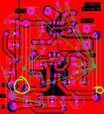
The star grounding scheme is divided into three (see attached). Two sections were intended to be the clean gnd which connect to the power supply ground. I'm not sure how effective this is 😉
I'm using the buffer (half the NE5532P) as the source will not always have be consistent (i.e guitar and or various pedals, laptop, cd player etc.)
I've removed R11 and put it at the input to the buffer at 1kohm for RF interference immunity along with a 330pf cap parrallel to ground.
The NE5532p will also be replaced with the LM4562 but i dont have it in my parts library
The learning continues 😎
Cheers.
the Servo values were derived from the info in this topic here.
It simulated well but i haven't tried it in the real world yet.
The star grounding scheme is divided into three (see attached). Two sections were intended to be the clean gnd which connect to the power supply ground. I'm not sure how effective this is 😉
I'm using the buffer (half the NE5532P) as the source will not always have be consistent (i.e guitar and or various pedals, laptop, cd player etc.)
I've removed R11 and put it at the input to the buffer at 1kohm for RF interference immunity along with a 330pf cap parrallel to ground.
The NE5532p will also be replaced with the LM4562 but i dont have it in my parts library
The learning continues 😎
Cheers.
Attachments
correctable offset.
look at U1b.
the opamp tries to adjust the output so that both the input pins are at the same voltage.
Lets put 150mV on pin5 (from U1a).
with a gain of 2times the output will sit at 300mV.
The 1k+1k divider will have 150mV at the junction. This makes pin5=pin6 for voltage.
Pin6 of U4 will have to sit at [115+15+1] / 1 * 150mV=19.65V.
To produce this output the U4 supply will have to be ~+-22Vdc.
Your +-15Vdc supplies will allow correction of ~100mV of input offset.
Q.) is there any error in my arithmetic/logic?
I can up the regulators to 18v, so all opamps run at the same voltage. and the servo range increases 🙂
Hi,
with V1=1V, what is the voltage on pin6 of U4?
What about all the component values you have chosen? Some seem very odd.
The last thing you need to do is change the supply voltage.
with V1=1V, what is the voltage on pin6 of U4?
What about all the component values you have chosen? Some seem very odd.
The last thing you need to do is change the supply voltage.
from the simulation
v1 = 1v
u4 pin 6 = 261.228 v
voltage after R8 = 1.001v
voltage at the output from the circuit = 389uV.
Which component values do you not like ?
v1 = 1v
u4 pin 6 = 261.228 v
voltage after R8 = 1.001v
voltage at the output from the circuit = 389uV.
Which component values do you not like ?
Maybe a good coupling cap between the LM4780 and the preamp is enough. Scrap the dc servo. Might even sound better !😉
Ted205 said:It simulated well but
Ted205 said:from the simulation:
v1 = 1v
u4 pin 6 = 261.228 v
Which component values do you not like ?
AndrewT said:C2 is connected to the wrong end of R9.
What are R10 and R11 doing?
Why is R8 so much bigger than R9.
Why is C2 so much different from C3.
sorry if you're already fully aware of it, but if you want a good buffered pre check out the Pass Labs B1 Nelson's article, B1 thread
- Status
- Not open for further replies.
- Home
- Amplifiers
- Chip Amps
- BufferPreamp with servo