I've got an inverting LM3875 setup, with an OPA627 as a unity gain buffer followed by a low pass filter feeding the LM3875.
Now, I've got a small problem of a sorts, when I turn on the amp I get DC at the output, even with a DC blocking cap in front of the LM, if I connect the LM all by itself with nothing at the input, I get 0V DC. But when I measure I don't measure any DC coming from the OPA627, so I'm guessing it's the OPA627 oscilating, again, just a guess.
But what makes it strange, at least strange to me, is that if I turn on my source before I turn the amp on, all is fine, even if the source (CD player) isn't playing anything yet.
Any ideas, I'm open for sugestions...
JoeBob said:No, no pot.
So put the pot or something in, or always turn on the source first. Otherwise OPA’s input sees too high (if you have too tall resistor from OPA’s input to ground) or (almost) infinitely high impedance (if you have nothing there). And yes, that leads to oscillation.
Again, as SY said, if you could post schematic it could clarify the thing…
Pedja
Why do you use LPF (cap behind 700R)? OPA627 (BTW, FB should be connected to -input) does not oscillate in a circuit like this. Do not forget supply bypass capacitors (100nF//10uF) just at OPA627 pins no.4 and 7. But I guess that it is LM which oscillates, not the OPA627.
I think also that LP filter AFTER the first stage is a little odd. Normally you want to isolate from the nasty world the first thing you do.
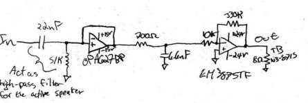
JoeBob said:here it is, excuse my poor drawing abilities...
The drawing or the circuit around the 627 seems wrong to me.
Are you using an inverting or non-inverting circuit for the buffer?
If you are implementing a voltage follower, the output should go to the inverting input. The input filter connects only to the non-inverting input.
If you are reversing your 1st stage, connecting input filter and output to the inverting pin, then the non-inverting pin should be grounded.
Which is it?
Carlos
In previous days I had a success simulating power on offsets, but the opamp buffered GC circuit (using OPA627 model) seems a bit weighty for my simulator. Using LM6172 model I did not saw anything to worry about (this is my report, not a wish to be responsible for damage…).
@ Nuuk:
Knowing that you are methodical and pedantic I wonder that you have omitted to indicate the inputs in the opamps. 😉
😉
@ Joe:
Make sure you are using the circuit as in the Nuuk’s schematic (OPA627’s minus input is up, plus input is down).
If you use the circuit as the high pas filter, IMHO it is better i.e. safer to put that high pass filtering cap to the OPA’s output.
Pedja
@ Nuuk:
Knowing that you are methodical and pedantic I wonder that you have omitted to indicate the inputs in the opamps.
😉 @ Joe:
Make sure you are using the circuit as in the Nuuk’s schematic (OPA627’s minus input is up, plus input is down).
If you use the circuit as the high pas filter, IMHO it is better i.e. safer to put that high pass filtering cap to the OPA’s output.
Pedja
Ummm.... ya, the OPA part is drawn wrong, it's wired up as a non-inverting unity gain buffer, output tied to - input, sorry for that, was in a hurry when I drew it.
Constant DC, well it goes positive then swings almost all the way negative. I get just a slight power off thump, barely noticable (this is when the source is turned on first).
Constant DC, well it goes positive then swings almost all the way negative. I get just a slight power off thump, barely noticable (this is when the source is turned on first).
Spooky Joe! That's pretty much what I found when I started off with my OPA627 buffer! I got round it by using a different PSU!
Actually, changing the PSU lead to such a problem, at least I think so. Originally I used just a 15V regulator, then I added a 24V regulator followed by the 15V regulator, so now I have a "pre-regulator". And now I've got the PSU working perfectly I notice this problem.
I don't know if before, during my testing, I always turned on the CD player first, or if it was the PSU causing the problem. But the problem is there now and I'd like to understand it, not jst fix it, I find it rather odd.
Because it's only when I turn it on, if I have the CD player on when I power up the amp, all is good, even if I turn off the CD player and change CDs...
Since these are active speakers, I think if I can't fix the problem what I'll do is just make them turn on when a signal is present, a signal-sensing turn-on switch, then it would always turn on after the CD player... Well, that's a last resort, and then I'd have to figure out how to do that...
I've toyed with it for enough today. I guess I'll give it a rest until tomorrow.
But if anyone has any ideas for what eles I should try, I'm up for it, changing the PSU slightly, adding a resistor on the input before the cap and a whole lot of all around changing things hasn't fixed anything yet.
But if anyone has any ideas for what eles I should try, I'm up for it, changing the PSU slightly, adding a resistor on the input before the cap and a whole lot of all around changing things hasn't fixed anything yet.
- Status
- Not open for further replies.
- Home
- Amplifiers
- Chip Amps
- Buffering problems.