I'm planning on building a new line preamp with a stepped volume control connected to a buffer, either the Pass B1 Buffer or a pair of ICs connected in voltage follower mode as I want no gain. However, after reviewing the specs of my system I'm wondering if a passive volume control might be an option enabling me to omit electronic circuitry altogether. I would appreciate any advice on this matter as I'm willing to go either way depending on the viewpoints advanced here. I realize the ultimate test would be to listen to both versions, but short of that, I'd be interested in your opinions.
My system consists of a Marantz CD player and an Audiolab AM/FM tuner connected through my present preamp to a Bryston 3B power amp. My present preamp is on the way out necessitating my need to replace it.
The output level of the CD player is 2V RMS and the output impedance is 200 ohms. It is connected to the preamp with a pair of 18" long interconnects.
The output level of the tuner is 700 mV RMS and the output impedance is 100 ohms. Interconnects to the preamp are also 18" long.
My power amp has an input sensitivity of 1V RMS for full output and an input impedance of 50K ohms. It is connected to the preamp with 3' long interconnects.
With a passive setup, I'm planning on using a 10K stepped attenuator. My reasoning is that this impedance is more than adequate for both sources but I'm not too sure how it would match up with my power amp's input impedance of 50K ohms. However, at least the output levels of the sources seem to indicate that voltage gain would not be required to reach full power output. As I said, any thoughts about this would be greatly appreciated. Should I end up going with buffered outputs I would probably use a 50K stepped attenuator.
I'd suggest that you start with either a 10K stepped attenuator from eBay or an ALPS 27 10K pot. A 10K stepped attenuator or potentiometer will do fine with your sources and power amp.
I've been using "passive volume controls" for many years, mainly because I don't want the extra distortion added by an active preamp. In the last few months, however, in connection with building two class AB amps, I've tried several SS and tube preamps from China and also an OPA1622 evaluation board, as well as some passive volume control devices using stepped attenuators (some home-made and some from China) and ALPS pots. All the active preamps sound different among themselves and from the passive volume attenuators. The very frustrating thing is that even the passive volume attenuators sound different from each other, although they are closer in "flavor" compared to the active preamps.
If you must have some gain, I'd suggest trying this preamp kit, but with the included NE5532 op amp swapped to LM4562.
Assembled Douk Audio Full DC Shielded OP-AMP HiFi Pre-amplifier Preamp Board | eBay
The circuit of this preamp is as simple as it gets -- just a text-book application of an op amp with a gain of 3. Of all the active preamps I've tried, this one sounds the closest to the passive volume attenuators. I am using it now to drive an amp that has an input impedance of around 12KOhm.
Cheers,
Kurt
Last edited:
There's an excellent presentation and discussion of passive volume control issues and system considerations in the sticky thread at the top of the Analog Line Level forum.
With a passive setup, I'm planning on using a 10K stepped attenuator. My reasoning is that
this impedance is more than adequate for both sources but I'm not too sure how it would match up
with my power amp's input impedance of 50K ohms.
The 10k control will have a maximum output resistance of 2.5k. This is fine for use with the amplifier's
50k input impedance. I encourage you to use the passive method, with high quality cables to the amplifier.
OP, what's wrong with your preamp anyway (and what is it)? These things tend to be among the more repairable kinds of device, and if there is no reason to suspect subpar circuit performance (even when fully working, I mean) I'd be inclined to keep it.
That said, the passive pre with a 10k pot would probably work out alright in this case. Just keep the cable length to the power amp relatively low. 2..3' of decent coax should be fine, I wouldn't use the thinnest and cheapest cable.
That said, the passive pre with a 10k pot would probably work out alright in this case. Just keep the cable length to the power amp relatively low. 2..3' of decent coax should be fine, I wouldn't use the thinnest and cheapest cable.
10k is really rather a low input impedance for a pre-amp. In my experience this results in loss in dynamics. I'd suggest using a buffer prior to the stepped attenuator.
Hi abraxalito,
The Chinese preamp kit linked to in my message actually has a 50K ALPS 27 pot at the input (flowed by the G=3 op amp circuit). Would the use of a 50K pot address your concern about the loss in dynamics?
If the buffer is put at the front, what attenuator value would you choose?
Do you see a reason not to use a value that is much lower than 10K?
Also interested in hearing your thoughts regarding why a 10K attenuator at the input would result in loss in dynamics, when the output impedance of the source is around 200ohm, which is only 2% of the load seen by the source output stage. Is this loss of dynamics caused by the inability of the source to drive a 10K load, the variable input impedance of the amp (which does not seem likely as it is directly after the buffer), or something else?
USE the 10k pot.
IF there's ...any... issue? Fit a Passdiy.com B1 buffer kit (50$) betwixt the pot and the Amp.
Less is better.. until proven otherwise.
IF there's ...any... issue? Fit a Passdiy.com B1 buffer kit (50$) betwixt the pot and the Amp.
Less is better.. until proven otherwise.
The Chinese preamp kit linked to in my message actually has a 50K ALPS 27 pot at the input (flowed by the G=3 op amp circuit). Would the use of a 50K pot address your concern about the loss in dynamics?
If there's an opamp circuit following the pot the likelihood is that's going to be something of a bottleneck in dynamics. I use classA gain stages myself to get around the audible issues of opamps with their classAB outputs.
So 50k pot isn't going to be a dynamics problem given the opamp following it. If you change the opamp to something classA then its worth going for higher input impedance (I'd suggest 200k).
If the buffer is put at the front, what attenuator value would you choose?
Do you see a reason not to use a value that is much lower than 10K?
With a buffer I reckon a 10k attenuator is fine, though you could go down to 5k to get better drive to the next stage. Myself I'd use a TVC though as this gives lower output impedance.
Also interested in hearing your thoughts regarding why a 10K attenuator at the input would result in loss in dynamics, when the output impedance of the source is around 200ohm, which is only 2% of the load seen by the source output stage. Is this loss of dynamics caused by the inability of the source to drive a 10K load, the variable input impedance of the amp (which does not seem likely as it is directly after the buffer), or something else?
As I've hinted at above, its down to the fact that the vast majority of CD players have opamps for outputs, and those opamps run classAB meaning that when they're driving any kind of load the power supply currents are nasty correlated harmonics of the music signal. The decoupling on most opamps doesn't attenuate this hash sufficiently and it gets perceived as dynamics loss.
"The decoupling on most opamps doesn't attenuate this hash sufficiently and it gets perceived as dynamics loss."
This is very interesting. Thanks for the tip. I am going to start playing with the power supply of my DAC, which has an op amp (LM4562) as the output device. I may also try biasing the op amp into class A.
This is very interesting. Thanks for the tip. I am going to start playing with the power supply of my DAC, which has an op amp (LM4562) as the output device. I may also try biasing the op amp into class A.
Last edited:
You're welcome Kurt. You'll find playing with decoupling is something of a can of worms because typical layouts don't make any attempt to separate out power ground from signal ground. When they're merged (as they almost invariably are) noise on the supply couples to noise on the signal ground.
If you increase the decoupling caps you also increase the noise on your signal ground. So then you need to start hacking the PCB to separate out the grounds..... The rabbit hole goes quite deep 😀
If you increase the decoupling caps you also increase the noise on your signal ground. So then you need to start hacking the PCB to separate out the grounds..... The rabbit hole goes quite deep 😀
For a practical example, you can dig up that Sansui AU-5900 thread from like November in Solid State. This mid-'70s integrated amp is quite noisy stock (espexially on the overly-hot headphone out), which was traced to be coming from the preamp supply. Turns out PSRR of the preamp circuitry is not good in sim in addition to a noisy regulator, and trying to filter the supply locally kinda backfired, with noise even getting worse than before at higher volumes. Closer inspection revealed decidedly non-star grounding in the area in question, so apparently the filtering did its best to insert power supply noise into the ground. Some rerouting including addition of a dedicated power ground plus quieting down the regulator finally yielded the desired result.
I have a hunch that the same issue is also making the occasional consumer audio device more noisy than it should be. Large single-layer boards and daughtercards are ideal conditions for highish return impedance, and the effect is especially bad when supply impedance is kept low (some series resistance in the supplies potentially reduces the effect quite dramatically, so now you know why some designers prefer RC filtering).
Still, most audio devices I've come across tended to sound just fine, so I don't buy it's quite the problem it's made out to be.
Last edited:
Thanks everyone for your helpful comments and suggestions. I had read the sticky at the head of this section prior to posting this thread and, following its content, had concluded that a passive attenuator might be suitable for my system given its specifications. However, I did want some kind of confirmation before I went ahead.
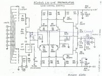
My current preamp has started exhibiting distorted sound which makes listening to music unbearable. It is an Acurus L10 Line model which I believe is no longer made or sold here. I have no schematic for it and no test instruments (other than a true RMS digital multimeter) so repairing it myself is not an option. Additionally, I would like to build my own unit so this gives me the perfect excuse.
Following some of your comments, I have decided to build a 10K ohm passive step attenuator as my control unit. I will also add a selector switch allowing at least 2-inputs for my CD player and FM/AM tuner. I would like to try a non-electronic solution first. If I like the result, all well and good. If not, I'll next build a unit with a buffer such as the Pass B1, or one with op amps.
I'm looking forward to the outcome.
Again, thanks to everyone for your kind replies.
The Mesmerize version of the DCB1 is an excellent selector, Buffered vol pot and PSU combined on one PCB.
Your 10k vol pot can be wired into the Mesmerize, even if the pinouts do not exactly match.
Your 10k vol pot can be wired into the Mesmerize, even if the pinouts do not exactly match.
Here's an older thread on said Acurus L10 amp with at least a partial schematic:
http://www.diyaudio.com/forums/analog-line-level/241123-acurus-l10-preamp-mods-schematic.html
The power supply section (where I suspect the problem lies) is not depicted but we can infer a few things from the details mentioned. The discrete voltage regulators do not look too complex, shouldn't be too hard to reverse engineer if needed. First of all I would look for the 1000µ buffer caps and 10 ohm dropper resistors on the regulated +/-18V supplies and measure voltages there. Presumably one of the rails has a problem, maybe a cooked transistor or fried zener diode.
Here's an older thread on said Acurus L10 amp with at least a partial schematic:
http://www.diyaudio.com/forums/analog-line-level/241123-acurus-l10-preamp-mods-schematic.html
The power supply section (where I suspect the problem lies) is not depicted but we can infer a few things from the details mentioned. The discrete voltage regulators do not look too complex, shouldn't be too hard to reverse engineer if needed. First of all I would look for the 1000µ buffer caps and 10 ohm dropper resistors on the regulated +/-18V supplies and measure voltages there. Presumably one of the rails has a problem, maybe a cooked transistor or fried zener diode.
Thank you very much, your help is much appreciated. Now that I have the schematic, and your suggestions as to how to proceed, I may attempt to make repairs myself. At least I'll give it a try and see what I can do. Nothing ventured, nothing gained and if it doesn't work out I still have the option of building a passive volume control.
Last edited:
The Truth About Passive Pre-amps
check out this paper:
The Truth About Passive Pre-Amps
What about the claim “Passive pre-amps can’t drive the cable” ??
In the above URL I read this :
This is the myth which is commonly quoted. It stems from a mis-understanding of the output impedance of passive pre-amps. This is where most of the criticism of passive pre-amps comes from - the idea that they don't have any circuitry to drive cables. It’s nonsense. The reason why low output impedance is a good thing is because the output impedance of a device will form a potential divider with whatever impedance is connected to the output (the load impedance). If the output impedance was zero, then the divider would have no effect and there would be no loss of signal. If the output impedance was higher than zero, then some of the signal voltage would be lost. The worst case is when the load impedance is reactive rather than resistive. Most commonly, the capacitance of the interconnecting cable forms a reactive element, and that capacitance, combined with the non-zero output impedance forms a low pass filter. ie the high frequencies are rolled off. In PA applications where cable runs may be over 100 metres (from stage to mixing desk, for example) the capacitance of the cable can be considerable and mustn’t be overlooked. The total capacitance of 100m of good cable would be about 10nF (nano farads) -maybe up to 30nF for cheaper cable. 30nF of capacitance loading a passive pre-amp would indeed limit the high frequencies significantly, however, a 1 metre length of hi-fi interconnect cable would be more like 100pF (pico farads). That is a much smaller amount of capacitance. Loading the Indus SE with 100pF doesn’t affect the audio bandwidth. In fact the bandwidth will extend to well over 100kHz. This is because the maximum output impedance of the Indus is 3750 ohms.
Compare that output impedance to the many valve pre-amps which follow minimalist design principles. They tend to have very high output impedances - certainly higher than 3750 ohms and quite commonly 10k or 20k or even more. They have HF roll off problems much worse than a passive pre-amp. The truth is that when using a passive pre-amp the source component (eg CD player) is the thing that drives the cable. It drives the cable through the (passive) pre-amp, with the pre-amp adding only insignificantly to the output impedance. A valve pre-amp (or any other active pre-amp) with a high output impedance has less ability to drive cable than a well designed passive.
My own experience is the same, but even with signal leads arround 1m a low capacity version is important.
Long wires needs a buffer - so I think. Therefore a simply circuit with low voltage and high idle current provides best results in sonic quality.
For a friend I have realized this approach from Andrea Ciuffoli's Power follower 99 for his buffered Pre-Amp:
http://www.audiodesignguide.com/articles/Power_Follower/art2.jpg
It runs with 1A idle current/each channel and 9Vdd.
A Penny & Giles potentiometer from 80s is in use (same model as in use in Jeff Rowland's Coherence ONE.
Anywhere here I have upload images.
This preamp was and is currently still a knockout.
I have found the images - go to post #1 under
Delivery Source wanted for this Cinch female Connectors in special Outline
The Truth About Passive Pre-Amps did not tell the whole truth, I'm afraid, by missing out the low pass filter seen in most feedback power amps at the input, usually made of a series resistor and a shunt capacitor. The output resistance of a passive preamp would add up to that series resistor to become part of the low pass filter, hence an altered cutoff frequency. There may or may not be consequences depending on the design of that low pass filter, the larger the value of the capacitance, the more pronounced the alteration to the cutoff frequency caused by the output impedance of a passive preamp.
A worse case scenario would be a low pass filter made of 1Kohm and 1nF cutting off at 160KHz, adding up a 4Kohm output impedance from a passive preamp and the filter would cut off at 32KHz instead, rolling off the high end of the audio band.
Many modern power amps, however, have the cutoff far out to several hundred KHz, much less likely to have audio band response affected. So the words would be, look at the schematic diagram and do some calculation, and decide accordingly.
A volume pot has a varied output impedance depending on the wiper position, when driven by a low impedance source, the pot output impedance is lowest at low end and high end volume, and highest in the midrange volume, about 1/4 its nominal resistance. So when you turn the volume knob of a passive preamp you slide the cutoff of that LPF as well.
- Home
- Source & Line
- Analog Line Level
- Buffered Preamp or Passive Volume Control?