CM distortion is likely to be mainly second-order (like most distortions) so percentage distortion will probably be proportional to CM voltage, and so proportional to signal level.
So with 0.015% @ 10k source impedance, no compensation resistor in the feedback and 3V signallevel this buffer distortion would drop at least a magnitude with an input of 0,3V or less where I would reach about 96-98 dB SPL in my listening seat anf THD of the speakers reach 1% or even more.
I did some testing with OPA2134 at lower levels, but I am limited both in lowest distortion level and.frequency range by my M-Audio Transit , but there is a clear reduction of distortion at lower signal levels.
And it is mostly second order that is visible. I will try to add some spectrum later and perhaps see if I can resolve any difference with added cancelation resistors.
To be continued...
And it is mostly second order that is visible. I will try to add some spectrum later and perhaps see if I can resolve any difference with added cancelation resistors.
To be continued...
Here I attach some measurements from Arta.
My setup lack somewhat of resolution, limited by Arta and the alligatorclips all over the breadboard...
But 0dB signal level is 1,35V output, thus -20 dB is 0,135V, a more commonly encountered voltage in Hifi than 10Vrms.
Setup is a simple OPA2134 driven by +-12V, and a 12k resistor between Transit Line Out and + in of one of the op. The other has both inputs tied to ground.
Output of OP is going to the Line in of the Transit, and is loaded with 10k to ground. Fs = 48000 kHz, resolution is 24 bit.
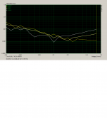
First picture is the distortion vs level at 1, 5 and 10 kHz.
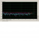
Second pirture is the spectra for an input of 0,135V , -20dB
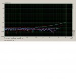
Third is for -1dB.
Interesting is how CM voltage makes THD take of at higher frequencies. At the lower input, noise and resolution limitations increase the total THD regardless of frequency but there is far less of CM distortion wich rises at higher frequencies. That is how I interpret the curves. Tomorrow I will try to repeat with a 5,6k cancellation resistor in the feedback path.
Inputs?
My setup lack somewhat of resolution, limited by Arta and the alligatorclips all over the breadboard...
But 0dB signal level is 1,35V output, thus -20 dB is 0,135V, a more commonly encountered voltage in Hifi than 10Vrms.
Setup is a simple OPA2134 driven by +-12V, and a 12k resistor between Transit Line Out and + in of one of the op. The other has both inputs tied to ground.
Output of OP is going to the Line in of the Transit, and is loaded with 10k to ground. Fs = 48000 kHz, resolution is 24 bit.
First picture is the distortion vs level at 1, 5 and 10 kHz.
Second pirture is the spectra for an input of 0,135V , -20dB
Third is for -1dB.
Interesting is how CM voltage makes THD take of at higher frequencies. At the lower input, noise and resolution limitations increase the total THD regardless of frequency but there is far less of CM distortion wich rises at higher frequencies. That is how I interpret the curves. Tomorrow I will try to repeat with a 5,6k cancellation resistor in the feedback path.
Inputs?
Attachments
- Status
- Not open for further replies.