Hi,
The info I seek may be buried here somewhere, but I couldn't find it. The problem is a slight amount of hum. By slight, I mean about 3mv ac on the output of the amp (both inverted and non-inverted). I didn't care much before as the speakers I were using were not real efficient and the hum was low enough to be inaudible until very close. I now have an application with more efficient speakers and would like to minimize hum.
The chip-amp part, built on Brian GT's original boards doesn't seem to be the problem. Both amps have discreet jfet buffers, ala Pedja. If I short the buffer output to the amp, I get a fraction of a milliamp hum at the ampt output. No change (that is, the same 3ma or so)if I short the input to the buffer. So, the slight hum I get is from the buffer itself. Any obvious layout issues anyone is aware of, that I should check before I dig in and start probing around? One buffer is powered by three-terminal regulators on the board the other set is powered by a discreet ps separate from the buffer board. Both amps use Pedja's discreet regulator supply as the main supply.
Sheldon
It could be (I don't know what the power supply rejection is like for that circuit), but more likely, it's a grounding issue. Power supply ripple is being impressed on the signal.
SY said:It could be (I don't know what the power supply rejection is like for that circuit), but more likely, it's a grounding issue. Power supply ripple is being impressed on the signal.
You're probably right on that score. I think the psrr is fairly good. And in any event, there ain't much ripple. If I use my multimeter and put a 0.1uf cap in series with the probe, I measure about 3mv. Plus that supply on the one amp then supplies 7815/7915 for the buffer, I measure about 1mv there. I put caps after the regulators (about 10uf, I think) and I wonder if that might be a source of the ground noise. I'll play today. I can test with 9v batteries too.
It's a bit mysterious, as I have the grounds lifted from the mains ground with a 25ohm resistor, but maybe I've made some other error. Time to dig in.
Sheldon
Well, I dug in. Checked out everything I could think of. The grounding scheme seemed fine. One last test. I disconnected the power supply and powered it up from another clone power supply. Noise went from 3mv to 0.2mv.
Conclusion? I've just got too much stuff in too little space and I'm getting inductive coupling somewhere. Probably doesn't help the case is aluminum (one of Peter's nice cabinets). It's the buffers that seem to pick up the noise. In the second amp (the one I used for power) I get about 0.6ma noise, but the buffers in that one are further away from any ac source. Looks like the solution will be to make a separate case for the power supply.
sheldon
Could you put shematic and layout pictures here?
It would be much easier to track the problem with the grounding.
It would be much easier to track the problem with the grounding.
If you're picking up mains signals couldn't you just shield the entire input buffer with some copper foil? Or if you want another way build the entire input inside an altoids tin.
Tell us how it works out. I'm planning on using the JFET buffer myself.
Tell us how it works out. I'm planning on using the JFET buffer myself.
Sheldon, following this thread, and reading Pedja's pages again led me to the thread where I think it was you who first put forward the idea of shunting the output of the buffers to ground while they warmed up.
So this is just to say thank you for that idea which works well. I have written up all the details here . 😉
So this is just to say thank you for that idea which works well. I have written up all the details here . 😉
Nuuk said:Sheldon, following this thread, and reading Pedja's pages again led me to the thread where I think it was you who first put forward the idea of shunting the output of the buffers to ground while they warmed up.
So this is just to say thank you for that idea which works well. I have written up all the details here . 😉
Instead of that fancy 555/relay circuit how about a simple capacitor charging circuit to hold on the mute feature of the chip until everything is warm? I mean, as far as I know all this bad noise during power up won't hurt anything, it just sounds bad.
Please correct me if I'm wrong.
Instead of that fancy 555/relay circuit how about a simple capacitor charging circuit to hold on the mute feature of the chip until everything is warm? I mean, as far as I know all this bad noise during power up won't hurt anything, it just sounds bad.
The noise may not hurt anything but it makes a nasty sound that I don't want if I can help it (and don't want coming from my speakers).
The 555 circuit only uses a few components, is simple to build and incorporate in a buffer/preamp, and 'does what it says on the can' so I am happy to use it and recommend it! 😉
If you don't have any 555's lying around in your junk box there is a very simple circuit which uses a single transistor to toggle the relay. Not as accurate timing wise, but it sure works for me.
I am using one in a gainclone for myuting purposes, and one in my big valve amp to soft start it.
Shoog
I am using one in a gainclone for myuting purposes, and one in my big valve amp to soft start it.
Shoog
If you don't have any 555's lying around in your junk box there is a very simple circuit which uses a single transistor to toggle the relay. Not as accurate timing wise, but it sure works for me.
I expect diyAudio has just enough bandwidth for such a design to be posted here Shoog! 😀
Nuuk said:Sheldon, following this thread, and reading Pedja's pages again led me to the thread where I think it was you who first put forward the idea of shunting the output of the buffers to ground while they warmed up.
So this is just to say thank you for that idea which works well. I have written up all the details here . 😉
I think that probably was me. I used a small bridge, a 115v relay a couple of resistors and a cap. However, since I'm relocating the power supply, I'll convert over to the 555 version. Might as well get rid of all the ac in the main chassis. And yeah Shoog, it's not nice to tease.
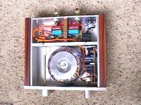
Asogorath, shielding would probably work, but no room, as the pic shows. Also, this amp is 3875, so no mute pin. I did use the mute pin/cap method for the other amp, which is 3886.
Fallow, I checked and rechecked the grounds. I'm pretty sure that, as my test showed, the problem is proximity to ac sources. In the other amp (with lower noise) I was able to locate the buffers in a corner away from AC, as I used a separate box for volume control and source switching.
Pic. of problem amp:
The buffers are the small boards with a brown and a blue cap, sitting over the chipamp boards. What the picture doesn't show is the delay circuit, which I put in later next to the transformer, opposite the ps. Nuuk's version would be more compact and only involve dc so, on second thought, there is a chance I could squeeze the buffers in over there. Might have to shield them from the transformer though. Any thoughts on that issue?
Attachments
Nuuk's version would be more compact and only involve dc so, on second thought, there is a chance I could squeeze the buffers in over there. Might have to shield them from the transformer though. Any thoughts on that issue?
I think that the only way to find out for sure is to try it! Some have reported putting circuits tight against the mains transformers with no ill-effects.

Hmm, I think I have the solution. One thing I hadn't considered was the proximity of the pot to the power wiring. I have the wires going under the pot and into the other side of the chassis. I disconnected them from the power entry module and moved them well away to test with clip leads. Noise gone. So it's actually the pot acting as an antenna.
It looks like a little work with a drill and file to make a new route, and I'm in business. I think I'll still convert to the ss delay circuit - thanks Nuuk.
Sheldon
It looks like a little work with a drill and file to make a new route, and I'm in business. I think I'll still convert to the ss delay circuit - thanks Nuuk.
Sheldon
Nice that you found the problem, and cool that the solution is easy.
I was looking for the layout of your power source, and next time should ask
the whole picture, including the wire routing, for problem resolving.
I was looking for the layout of your power source, and next time should ask
the whole picture, including the wire routing, for problem resolving.
fallow said:Nice that you found the problem, and cool that the solution is easy.
I was looking for the layout of your power source, and next time should ask
the whole picture, including the wire routing, for problem resolving.
I don't have a camera handy, so I can't show the details. But it goes as follows: The entry module (with fuse) is located in the far corner at the back of the chassis. You can use one with a switch. I used a separate switch right next to the module. The 120 ac wires then run along the bottom corner of the chassis, to the front, where they connect to the transformer. You can see in that picture I posted, that originally the AC wires go under the pot (black cube mounted on the back right hand side of the chassis divider). I changed this to keep the AC away from the pot.
Near the front of the chassis, the transformer secondaries then connect to the diode bridges. From the picture you can see - front to back on the regulated supply (Pedja's discreet reg.) - diodes, caps, transistors, and next to the divider in the chassis, the heat sinks. So the AC goes from the entry module, along the botttom corner to the front of the chassis. Everything from then on, back to the amps is DC.
As for the rest of the grounding scheme, I connected Brian GT's boards as labeled, signal ground to sig ground, power ground to pwr gnd, etc., for each channel. The two boards were connected together with a single 1mm bare copper wire from chassis gndl to chassis gndr. The power supply ground was connected to the center of that wire. Also connected to that same point was a wire to the rear center of the chassis. At the connection point on the chassist was a connection to mains earth. The RCA inputs and speaker outputs are isolated from the chassis. The RCA grounds are connected via the pot to signal ground.
At this point I get about 1/2 mv of noise. Your ear has to be right on the speaker cone to hear that. That's fine for my use, but I could probably get to half of that with a larger chassis or remote ps.
One added note: I was seeing up to 4mv noise on one channel with the pot at the zero position or full on position. Adding a 1k resistor to the input of the buffer got rid of that. That's the optional R3 resistor in Pedja's jfet buffer description.
Sheldon
how do you identify noises
Hallo I hope you can help with these noises... am a bit tired of looking for them...
I have active 6channel LM3886 setup. It makes a ZZZZZZ sound seems like 50Hz/ 100Hz the part coming through the tweets sound a bit higher though... it changes from quiet, to slightly offensive at 2m away (time of day dependant... Night time and mornings are quite bad afternoon - early evening sometimes better. I took pre - power to friends house (I live in flat) It changed to almost unnoticable as in you can hear same type of sound only at speaker - ear against it. It doesn't change with volume control. I can also hear light switches and washing machines tick through my speakers... If I use really well regulated thel design phonostage the hum is as loud as the music... ihave really nicely specced transformers... as far as I know, but they hummm... the zzzzz is present with pre unconnected and switched off as well.
I have looked for ground loops (in signals earths, power earths - even disconnected the big one to make sure) , I have a serious star ground, I have separate reg psu's per active filter (one for each channel) separate enclosure for pre and power. My power and signal leads far apart or at 90 deg angles. I have stepdown transformers in separate box (for pre-power and cd) (240V down to 230V). all with filter caps everywhere, big ones & small ones (my wall socket reads 240 V... almost all the time and we are at 50 Hz)
All this has achieved was get the hummm to go zzzzzz... i.e. purify the zzzzz.
I want to split the psu to a floating ground / transformer? after reading the unreg snubbered PSU suggested reading have parts.
Any other advice?
Andre'
Nuuk said:
I expect diyAudio has just enough bandwidth for such a design to be posted here Shoog! 😀
Here are three possibilities. The just the coil for the relay is shown in each schematic. For stereo a DPDT relay would generally be needed, unless you can get an NC DPST (contacts closed with power off).
The BJT's are shown as a darlington pair, as you'd probably need that to have adequate current drive with a large base resistor. You could use a larger resister and larger cap, or just use a mosfet. I have not built the first two the the idea should work and someone will jump in with corrections if I've goofed. Choose voltages to match your relay (ideally relay matched to B+, so you won't need to drop voltage). And choose a relay with relative high winding resistance, to minimize current draw. Most relays wil switch on with about 2/3 the rated voltage.
The third version is what I have. The 115v relay switches on at about 40v. The time constant (time to reach 67% of final voltage, or Farads*ohms, which is 0.00022x4400 for this example) about 1 second. The actual time for switching for my relay is a little longer than that, as the maximum final voltage across the relay is about 55V, due the the two 2200 resistors.
As Shoog pointed out, these methods will not be as precise as the 555 chip, but it needs only to be longer than the buffer turn on time.
Sheldon
Attachments

- Status
- Not open for further replies.
- Home
- Amplifiers
- Chip Amps
- buffer noise