Kochkurov Maxim said:Some words about typicaly jitter values of differential transmitters/receivers, logic gates and digital isolators.
ADM1485 5ps RMS
SN65LVDS050 2ps RMS
MC10124/125 0.8ps RMS
100PU124/125 0.2ps (???) RMS
74LS family 8ps RMS per gate
74HC family 6ps RMS per gate
74ACT family 3ps RMS per gate
74AC family 2ps RMS per gate
74ABT family 0.8ps RMS per gate
MC100 family 1.5 ps RMS per gate (russian equivalent is K1500)
MC10 family 0.6ps RMS per gate (russian equivalent is K500)
100 family 0.1ps(???) RMS per gate (russian military aerospace equivalent of MC10)
AD8611 1 ps RMS (I measure only 5 items, results maybe has statisticaly unreliable)
ISO150 4 ps RMS
ADUM1100BR 4 ps RMS
100PU124, 100PU125 (russian transcription is 100ÏÓ124, 100ÏÓ125) is russian miitary aerospace equivalent of MC10124/125. It cost <1USD www.chip-dip.ru
Many thanks Kochkurov, that is a great benefit for us that don't
have equipment to measure jitter.
As suspected, ECL is the benchmark.
Have you measured any dig transformers such as Schott
or Scientific Conversion?
How did you do the measurements?
Cheers,
Terry
Have you measured any dig transformers such as Schott
No, I have not measured digital transformers, but I suppose that its jitter value approximately 20-50 ps. Unfortunately, I have no access to precision jitter measurement equipment now. I will get access to this equipment only in April.
How did you do the measurements?
I used Agilent phase noise measurement equipment with Rhode & Shcwartz referense oscillator. This equipment cost about 100000$ and very hardly get access to it . Now, I have only Tektronix digital scope in my laboratory, but its jitter measure floor is 50ps.
F.a AC logic sounding worse than HC.
It's not problem of IC, it's problem of its mounting and decoupling.
But I´dont undestand your web page becouse it is in russian
It's not my home page, it's URL of company which sell 100PU124/125 and other russian components. But this site only in russian. You may try e-mail them, maybe they'll send you this IC. The K500 family (equivalent of MC10) in Russia cost about 0.2USD, OC100 family (military aerospace equivalent of MC10, lowest jitter in the world, golded SMD package) cost about 2.5USD. I have some this IC, but I can not send this to you because I don't trust russian customs service.
feed it backwards.......
I want to do something like this.....but I am not sure how to do it right.
The DAC has system-clock input, but no output. If I feed the DAC directly from a Tent, or KC7, the signal that should go back to my player could NOT be connected to the clock in parallell....right ?
I need some kind of buffer, maybe the 74HC125 will do here to, but do I feed the DAC, and the logic with the same signal directly ??????????????
How will the SMD-part and "one-port"-logic 74AHCT1G125, or 74AHC1G125 do here ?
Lyra
Guido Tent said:
Suggestion: Place the master clock close to te DAC ad feed it backwards.......
Ciao
I want to do something like this.....but I am not sure how to do it right.
The DAC has system-clock input, but no output. If I feed the DAC directly from a Tent, or KC7, the signal that should go back to my player could NOT be connected to the clock in parallell....right ?
I need some kind of buffer, maybe the 74HC125 will do here to, but do I feed the DAC, and the logic with the same signal directly ??????????????
How will the SMD-part and "one-port"-logic 74AHCT1G125, or 74AHC1G125 do here ?
With this logic there are onle one port pr. package, but I am not sure AHCT, and AHC will do.<..... and NEVER use more than one inverter per package (use the one closest to the gnd pin), >
Lyra
Attachments
Terry, Kochkurov Maxim
I just have not found this to be true that jitter is generated in many ways and it’s not always a function of the rise time of the gate. There are to many other factor involved which you guy’s don seem interested in discussing.
Noise in circuits, decision points and transmissions lines, interface designs all play a great effect on jitter. The facts are parts that ultra fast switching can be a negative and can generate ringing on the output of the gate cause jitter. I do agree that reducing the width of decision point can be a good thing.
The one fact is, you can increase the frequency of the master clock and divide N and reduce the jitter Elso is that what you are doing. In addition, the jitter margin can improve by reduced by reclocking the data at a D flip flop before the filters and at the transmitter. In addition, at what point does this all become academic masturbation. Therefore, what if we have 30 40psec of jitter that not a big deal. A good PLL in front of the receiver can filter much of the stuff out.
😉
Re: feed it backwards.......
Take a Tent or KC7 at the freq you player needs. Divide the clock to the freq your dac needs. Feed the clocksignal back to the player. Use a async fifo before the dac. clock in on incoming i2s clock, clock out on the clock from the Tent or KC7.
There is a post around here from somebody who got away to do this without a fifo, but you could run into timing problems.
I did something like the above for tda1541 dacs with 11.xxx MHz player. Works fine, have a look here:
http://www.diyaudio.com/forums/showthread.php?threadid=8614&highlight=
Greetings,
Lyra said:
I want to do something like this.....but I am not sure how to do it right.
The DAC has system-clock input, but no output. If I feed the DAC directly from a Tent, or KC7, the signal that should go back to my player could NOT be connected to the clock in parallell....right ?
I need some kind of buffer, maybe the 74HC125 will do here to, but do I feed the DAC, and the logic with the same signal directly ??????????????
How will the SMD-part and "one-port"-logic 74AHCT1G125, or 74AHC1G125 do here ?
With this logic there are onle one port pr. package, but I am not sure AHCT, and AHC will do.
Lyra
Take a Tent or KC7 at the freq you player needs. Divide the clock to the freq your dac needs. Feed the clocksignal back to the player. Use a async fifo before the dac. clock in on incoming i2s clock, clock out on the clock from the Tent or KC7.
There is a post around here from somebody who got away to do this without a fifo, but you could run into timing problems.
I did something like the above for tda1541 dacs with 11.xxx MHz player. Works fine, have a look here:
http://www.diyaudio.com/forums/showthread.php?threadid=8614&highlight=
Greetings,
using fifo before dac
Guido and others,
I am going to use Guido's circuit (fifo only - no GAL etc.) to reclock I2S. Some questions:
1) how do I connect the EMPTY and HALF flag of the fifo?
2) Is it mandatory to reset the fifo upon power-up as reccomended in the datasheet ?
3) can I substitute 74HCT245 with a 74HC125 to buffer I2S input?
Thanks.
Paul
Does it have to be done that complicated ???
....especially when the clock-frequency required by the DAC is the same as for the CDP...?
What will happen if I just buffer (74HC125) the clock, and feed the "same" clock-signal to both the DAC and the CDP ?
This is the same as if I leave the clock in the CDP, isn't it ?
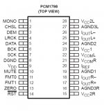
....and I don't need to split the I2S signal in right/ left signals as I am using a PCM1798 Stereo-DAC.....
Lyra
....especially when the clock-frequency required by the DAC is the same as for the CDP...?
What will happen if I just buffer (74HC125) the clock, and feed the "same" clock-signal to both the DAC and the CDP ?
This is the same as if I leave the clock in the CDP, isn't it ?
....and I don't need to split the I2S signal in right/ left signals as I am using a PCM1798 Stereo-DAC.....
Lyra
can I substitute 74HCT245 with a 74HC125 to buffer I2S input
I find it stange that some one would use a tri-state device for a line driver.
Paul,
1) After reset the fifo is filled with the incoming i2s clock. If it is half full, the half full line becomes low. This toggles the flipflop, go becomes high.
If GO is high, the fifo is read by a clock created with clkdiv2 and clkdiv4.
FIFOREAD =
/GO +
GO * CLKDIV2 * CLKDIV4 +
GO * /CLKDIV2 * /CLKDIV4
2) It is required that the input pins are nog changing during reset (iirc), hence the buffer in front of them with tristate output.
3) See 2, needed is tristate output with pull up resistors for reset.
I think i posted a schematic around here what i think it should be without a GAL. Iirc the clock for reading the fifo is created less complicated.
Lyra,
As i said before, it does not have to be so complicated. There is another post around here from a guy who has done this without fifo. But you might (!) run into timingproblems. Depends on timing: i2s direct or spdif inbetween. If the DAC clock toggles when the data toggles at the same time, you have a problem.
Jim, See 2/3
Regards,
Reclocking I2S
Guido,
thanks for answers. Your schematic at the link you posted is exactly what I needed.
Can you be a little more specific about timing problems with no-fifo reclocking? I am using I2S direct.
Regards.
Paul
Guido,
thanks for answers. Your schematic at the link you posted is exactly what I needed.
Can you be a little more specific about timing problems with no-fifo reclocking? I am using I2S direct.
Regards.
Paul
There was a post on this. Somebody posted a design without one. I gave some comments. In general: it can work, but depending on the timing (delay because of spdif or whatever) you could run into timingproblems.
Think he reclocked the incoming i2s data and ws, however the you could be clocking the signals just as they are changing state.
If that happens, one could use an inverter to solve it 😀
Use search on fifo, you might find it!
Guido
Think he reclocked the incoming i2s data and ws, however the you could be clocking the signals just as they are changing state.
If that happens, one could use an inverter to solve it 😀
Use search on fifo, you might find it!
Guido
Re: Reclocking I2S
Ciao Paolo,
I asked the same question to Elso and he replied that reclocking IIS doesn't bring almost anything, so probably is not worth the effort.
What DAC do you use (and on which player?)
Is this DAC placed inside or outside the CDP?
Cheers
Andrea
PS Sei di Milano città o della provincia?
Sandor said:Guido,
thanks for answers. Your schematic at the link you posted is exactly what I needed.
Can you be a little more specific about timing problems with no-fifo reclocking? I am using I2S direct.
Regards.
Paul
Ciao Paolo,
I asked the same question to Elso and he replied that reclocking IIS doesn't bring almost anything, so probably is not worth the effort.
What DAC do you use (and on which player?)
Is this DAC placed inside or outside the CDP?
Cheers
Andrea
PS Sei di Milano città o della provincia?

Andrea,
the CDPlayer is a Rotel 955 which has a decent transport (it reads CDRW with no problems and, having monitored the error flag, apparently with no errors).
The DAC board is inside the CDP, based on TDA1541A S1 battery operated; one 12V SLA for the +5V rail, two 12 V SLA in series, center tapped, for -5V and -15V, feeding TL431 shunt regulators.
The I2S inputs of the TDA1541 are directly connected to I2S output from SAA7310 decoder. Since I am going to move the DAC in a separate box I plan to build an interface based on LVDS tx/rx with cheap CAT5 cable and RJ45 connectors between transport and DAC. The DAC box will have a KC7 or Tent clock (11,XXXX Mhz) and Guido's fifo-based circuit.
Questions:
1) what about using the four twisted pair of a CAT5 cable as a transmission line for the three WS-BCK-DATA signals and the clock going back to SAA7310?
2) Any suggestion for the LVDS drivers, possibly in a DIP package?
Ciao.
Paul
P.S. Sono di Milano ma attualmente vivo in Toscana.
guido said:There was a post on this. Somebody posted a design without one. I gave some comments. In general: it can work, but depending on the timing (delay because of spdif or whatever) you could run into timingproblems.
Think he reclocked the incoming i2s data and ws, however the you could be clocking the signals just as they are changing state.
If that happens, one could use an inverter to solve it 😀
Use search on fifo, you might find it!
Guido
http://www.diyaudio.com/forums/showthread.php?threadid=19623&perpage=15&highlight=&pagenumber=1
Kochkurov Maxim said:I don't advice to use coax cable for transmit digital data if phase noise value of received signal is important. In this case differential transmitters/receivers and twisted pair provide lower phase noise than the coax. I usually use LVDS, PECL or RS485 transmitters/receivers, which has very low jitter (about 2ps) and more tolerants to power supply or coupling noises than emitter followers.
What is the best way of doing this....RS485 ??
If I use RS485, and want to use an extern DAC feeding this with I2S.signals (without S/PDIF)....and a clock signal back to the transport, 4 signals in all....
........could I use a shielded CAT5 patch-cable inbetween the CDP and the DAC ????
This would be a "nice" sollution instead of four coax-cables and keep remembering which one is which...
Lyra
PS: I didn't see the post from Sandor prior to posting, but it is a quite similar thought......
RS485 is one way, but likely not the best way.What is the best way of doing this....RS485 ??
Try something like the National DS90LV047A Quad LVDS Tx and DS90LV048A Quad LVDS Rx or the TI SN65LVDS047 Quad LVDS Tx and SN65LVDS048A Quad LVDS Rx. All of these have flo-thru pinouts (inputs on one side and outputs on the other) making them easy to build a PCB for. They are compatible, BTW (e.g. TI Tx with National Rx). Quad LVDS is perfect for use with Cat-5. But if you will be using regular ethernet cables, remember that the two inside pairs are wired funny - one pair on pins 3 & 6, the other pair on pins 4 & 5; the intuitive way would be 3 & 4 and 5 & 6. If you build your own cables, this is not a problem, but otherwise, make sure to route the signals to the appropriate pins on the RJ45 connector.
Hi,
I try to build a PCM2707 and PCM1798 in two seperate boxes. PCM2707 will output I2S signal to PCM1798 connected using a CAT5 cable for LRCLK, DATA, BCK AND SCK.
Some questions need advise:
1) Which format is better for connection using cable? I2S or SPDIF? I chose I2S because i got the impression from the forum that it is much better than SPDIF.
2) From the discussion above, SCK is not present in the transmission because NOS DAC doesn't required it. But in my case, I need to transmit SCK. What will be the problem if I transmit SCK using cable?
3) Is buffering the I2S signal really neccessary when transmit using cable? If I use short cable lenght, can I ommit it?
Thanks in advance for your help.
😀
- Status
- Not open for further replies.
- Home
- Source & Line
- Digital Source
- Buffer choice for IIS Direct