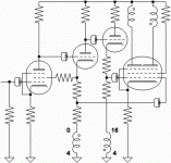
Here is a more classical construction using 2x6L6 in the output, 2xECF80 in the front end - this could be directly adapted:
http://www.dissident-audio.com/PP_6L6/Sch-V21.gif
http://www.dissident-audio.com/PP_6L6/Sch-V21.gif
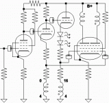
Throw a couple of local feedbacks at the
basic concept without changing too much.
Cathode resistor for the input Pentode.
Followed back with Cathode to Screen.
If strong feedback from the cathode kills
too much gain, you could tap the middle
of 2nd triode's plate resistor instead...
Schade's "plate to grid" for both G1's by
way of transformer secondaries... Which
might also help to linearize the iron.
And the common output cathode resistor
helps balance out any difference in drive
strengths, which is also a form of local
feedback. Though not truly "negative".
-------------------------------------------------
2nd Cathodyne drives from a higher DC.
Might need some diodes or whatever to
drop it down equal...
Attachments

After searching, it looks like some of the 6l6 guys are hitting the 50W mark in AB. That being the case, if your calculations indicate more than 35Wrms, I'd go with the 50W iron instead. 35W and under, you should be ok with the 25W iron running class AB.
None of the 829B load lines I've plotted in the past indicated more than 30Wrms. However, it was biased pretty heavily into class A.
None of the 829B load lines I've plotted in the past indicated more than 30Wrms. However, it was biased pretty heavily into class A.
What voltage are they running the output stage g2 and plate ? I was thinking 225/450 or thereabout (using power CT for g2 and front end) but maybe raising plate to 600V make sense to get more headroom out of AB1.After searching, it looks like some of the 6l6 guys are hitting the 50W mark in AB.
You're gonna need to drop at least 20V under the cathode.
With direct DC coupling, probably twice that...
With direct DC coupling, probably twice that...
What voltage are they running the output stage g2 and plate ?
The RCA 6l6 datasheet says fixed bias 450V plate 350V screen, aprox -30V grid, fixed bias with a 6k plate-to-plate load.
Unfortunately the 829B maximum screen voltage is 225V so those values could not be used. The 828B datasheet has a reference design on it that puts out 44W using fixed bias, with a B+ of 600V and a 13k plate-to-plate. 13k seems on the high side, I'd go lower then bring the B+ down to match.
Mind you, that these power numbers given are classified as class AB, but they are practically straight class B.
225V g2 limit is the reason I was thinking of a power supply with power secondary center tap providing 1/2 of the voltage for g2 and front end. I am thinking for using a power transformer that do 250/500 unloaded, this will drop a bit under load. With 450-500V on output plates maybe 25W OPT will do just fine.
225V g2 limit is the reason I was thinking of a power supply with power secondary center tap providing 1/2 of the voltage for g2 and front end. I am thinking for using a power transformer that do 250/500 unloaded, this will drop a bit under load. With 450-500V on output plates maybe 25W OPT will do just fine.
The g2 voltage is going to be the tricky part. The difference between the plate and g2 is large. You may be able to pull off what you are thinking. There are potential way's I could see that may work, and some ways that would make the transformer very unhappy.
With class A you would simply use a resistor+cap off the B+ because g2's DC draw is fairly constant so only AC impedance has to be low. However, in AB, DC screen grid current increases with signal. So the Vg2 would vary a lot depending on signal. It's critical to have a low DC and AC impedance for a class AB's g2 supply.
You can try the idea of the center tapped secondary, But simulate first. Don't do a voltage doubler scheme, as it would un-equally load the transformer in this circumstance. Your other options would be to do a regulator off the B+, use a separate winding, or go Class A with a lower plate voltage. The low g2 rating or this tube kind of makes AB2 start to look tempting.
Contrary to what I said earlier, the reference design in the 829B datasheet will put out about 5-8W in class A before crossing into B. The design in the 6L6 datasheet was pretty close to strait class B.
I think 460-500V plate with 200-225V g2 8-10k plate-to-plate would be the best "starting to tweak" range for AB1 with this tube. It will depend how much class A you want.
Personally I'd use the 25W 8kp-p edcor transformer. Then bring the plate voltage down until the load line intersects VGS=0 at the knee, which is about 50V. You should end up with 3X watts rms. Trying to squeeze more out of it would probably degrade sonics, especially going with undersized iron.
Would a Dynaco ST-70 trafo-set fit?
I'm not sure what the primary impedance is on those. More than likely, it would work for A2 or AB2, but be too low for A1 and AB1.
Contrary to what I said earlier, the reference design in the 829B datasheet will put out about 5-8W in class A before crossing into B. The design in the 6L6 datasheet was pretty close to strait class B.
On second glance, the 6l6 design puts out some class A as well. I was reading the datasheet quick the first time and mistook the zero signal g2 current for zero signal plate current.
Dynaco ST-70 trafo:
Transformer specs are: 4300 ohms CT primary with screen taps, 4,8 and 16 ohm secondary. 20 Hz to 20 KHz response at 35W, within 1 db, 30 to 15 KHz at 70 watts. Max DC per side (suggested) 80 ma. Exact same dimensions as the original A470 Dynaco transformer: Height 3 1/2 inches (88 mm) Width 3 inches (75 mm), depth over covers 4 inches (101 mm), mounting centers are 2 5/16 inches (59 mm) by 2 7/8 inches (72.5 mm). Shipping weight 7 pounds.
http://store.triodestore.com/noname.html
Arne K
I've heard they are excellent transformers.
Unfortunately, the max g2 voltage on the 829B is 225V. This limits the designer to higher impedance transformers if they want to stay in AB1 operation. For AB2 those would work.
Unfortunately, the max g2 voltage on the 829B is 225V. This limits the designer to higher impedance transformers if they want to stay in AB1 operation. For AB2 those would work.
Vladn,
Here's a good tutorial on plotting composite load lines, if you are not already familiar with it. Tweak with it a little and you should find your ideal point. And don't worry too much about the low signal distortion. Once you wrap some feedback around, it will help clear it up.
http://members.aol.com/sbench102/pent.html
I found a spice model for 829B and it may be easier to iterate in spice rather than using load curves because the goal is not to exceed plate power dissipation integrated over the sine wave cycle rather than for any point along the load curve (except for the zero signal steady state). In spice I can get rms plate current value over entire cycle and multiply it by load Z to get exact plate power dissipation. I can vary Z, plate voltage and input voltage until I get max output power without exceeding the plate dissipation over the entire cycle. Plus I can see the output THD from FFT (using phase splitter only, no pentode/NFB).
That should work if the model is accurate enough but I can probably get few curve traces in spice and compare it to the spec.
This should give a reasonable starting point. I'll post the results when done.
That should work if the model is accurate enough but I can probably get few curve traces in spice and compare it to the spec.
This should give a reasonable starting point. I'll post the results when done.
One question - is the OPT input Z specified between the plates or between the plate and a center tap ?
Did some curves for 829b in spice - they do match the flat region pretty well but the knee region is substantially different from the paper specs. So I guess any output stage THD analysis is useless but power / impedance analysis should be OK.
Did some curves for 829b in spice - they do match the flat region pretty well but the knee region is substantially different from the paper specs. So I guess any output stage THD analysis is useless but power / impedance analysis should be OK.
So I guess any output stage THD analysis is useless but power / impedance analysis should be OK.
Yes, that is usually the case. THD is useless, but power and impedance seem to be pretty accurate. Except, it doesn't account for losses in the transformer. Just assume real world will be a few watts less than simulated.
Push pull transformer impedance is given from plate to plate.
I've run some numbers for the output stage. Here are the results.
test conditions:
- class AB1 (no grid current);
- bias set for zero signal power dissipation of 10W per section;
- plate voltage swing down to 50V/180ma point (slightly above the knee for Ug1=0V characteristic);
- Psect (tube section plate power dissipation) computed by multiplying Up and Ip waveforms in spice and taking an average over a cycle;
- Pload was computed by computing Iload rms over a cycle in spice, squaring and multiplying it by Zload;
- front end is an ideal opamp, global NFB is used so that the power computations are done over a perfect sinewave output;
Up/Ug2, Ug1-bias, Ip-bias, Zload, Psect, Pload, full swing efficiency
450/225, -19.65V, 22ma, 9000ohm, 8.65W, 35.7W, 67%
600/225, -20.7V, 16.6ma, 12500ohm, 10.16W, 48.5W, 70.4%
and optimizing voltages for 8kohm OPT -
410/205, -17.2, 24ma, 8000ohm, 8.32W, 32.4W, 66%
- Status
- Not open for further replies.
- Home
- Amplifiers
- Tubes / Valves
- budget xformer for 829B pentode mode PP (class AB) ?