No I will be up in the mountains for a couple of weeks. I need to make up cables, and it will be a good test bed to learn how to measure distortion on my setup.
So I finally got around to powering mine up and having an issue. I had no power past the meanwell power module so I removed the 2 inductors and have a dead short on the positive side. I looked everything over pretty carefully with an inspection scope and can see no shorts or solder balls , any recommendations? Unfortunately I machined my case for it so if I can fix I will probably have to buy a populated one.
Bill
Bill
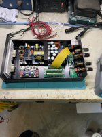
A dead short on positive rail can only come from a solder bridge or a bad component like a failed cap. Remove the small X7R C15 and C17 rail caps, and check polarity on the electrolytic input cap. Also check polarity of the power supply input to the DCDC. Please take some high res photos front and back and post them here and we will debug. It’s a very straightforward circuit and the PSU should be simple. We will fix it - don’t worry.
Is your +12v input same as photo (positive towards the front of the board)?

Is your +12v input same as photo (positive towards the front of the board)?
The polarity in is correct, the cap orientation is correct. I removed c17 and checked it. I will reflow all the cap pos to ground and send you some pictures. Any chance you can give me the pictures of the mask to help tracing.
Thanks for your prompt response ,
Bill
Thanks for your prompt response ,
Bill
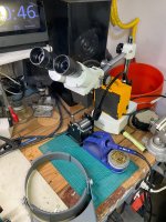
Well it was a pain but there was a ball of solder under u6 had to remove it and resolver it. Now I can move on with this project. The inspection scope payed off. It took 5 months to get machine done on face plate for meters but it is finally coming along.
Attachments
It is the 300W one offered by Eric in the market forum. I have bought 4 or 5 of them and gifted them to people. Way cheaper than most stuff I build and they can’t tell the difference. Thanks for the assistance it means a lot to me.
Bill
Bill
Last edited:
So I do have a 15+/- power from the amp however when I measured it it was 14.7+ and 15.3- would it be better to keep the meanwell power supply and run it off just the single +14 V or is that to much voltage for it?
Thanks
Bill
Thanks
Bill
I think you need to use a 7812 to drop the 14v or 14.7v to 12v before feeding the DCDC converter. It might work but not sure about longevity. Check the datasheet for the DCC converter and look for absolute max rating. In a car for example, “12v” is actually 13.7v since batteries typically make that when fully charged.
Spec sheet showed it good up to 18v, it runs cool. Voltage output is much more accurate than voltage from amp module. The input boards effects the sound of the amp module more than I expected. It brings in more mid to high frequency resolution, makes the amp brighter. Makes me more aware when you are designing an amp you have to look at them as a complete system, and randomly making changes may not be optimal. We will see after everything breaks in, I can always eq it if it is to bright. I was also surprised how much more the imaging improved.
Bill
Bill
@xrk971 Sorry to revive this thread, but as you have seen I am working on my own version of this board. This seems like the best place to ask this question.
I understand how the automatic switching works, but I am a bit unsure of what the G pin of the XLR section is actually connected to. From what I understand, it connects to the metal shell of the XLR plug itself. It also looks like there is a metal tap in the lower mounting screw hole that will effectively short the G pin to the chassis if this is metal. Is this correctly understood?

I would like to change the power input a bit to accept either 20-65V DC input or directly inputting +/-15-17V. The way I do this is by using a DPBW03G-15 DCDC converter instead of the one you use. It accepts 18-75V in and outputs +/-15V@3W(total). I would then use VINP through an LDO to make the 12V for the relay. But then the relay must also reference signal-GND to be able to turn on.

My issue with this is, then my signal-gnd will get shorted directly to chassis/XLR shield/connector housing. I am still new to this xlr/audio electronics world. Can anyone tell me if this connection would be okay? Or will I get issues with noise on the signal-GND? It is what is used to connect chassis to GND anyway. But will it be a probelm to have this connection twice?

If this does not work, then I have to ditch the abillity to input VP and VN directly and take the 12V for the relay from Vin (before the DCDC like you do).
Hope my question makes sense and isn't too stupid..
Thanks in advance!
I understand how the automatic switching works, but I am a bit unsure of what the G pin of the XLR section is actually connected to. From what I understand, it connects to the metal shell of the XLR plug itself. It also looks like there is a metal tap in the lower mounting screw hole that will effectively short the G pin to the chassis if this is metal. Is this correctly understood?
I would like to change the power input a bit to accept either 20-65V DC input or directly inputting +/-15-17V. The way I do this is by using a DPBW03G-15 DCDC converter instead of the one you use. It accepts 18-75V in and outputs +/-15V@3W(total). I would then use VINP through an LDO to make the 12V for the relay. But then the relay must also reference signal-GND to be able to turn on.
My issue with this is, then my signal-gnd will get shorted directly to chassis/XLR shield/connector housing. I am still new to this xlr/audio electronics world. Can anyone tell me if this connection would be okay? Or will I get issues with noise on the signal-GND? It is what is used to connect chassis to GND anyway. But will it be a probelm to have this connection twice?
If this does not work, then I have to ditch the abillity to input VP and VN directly and take the 12V for the relay from Vin (before the DCDC like you do).
Hope my question makes sense and isn't too stupid..
Thanks in advance!
The G pin is connected the “vampire” tap (a small tooth like protrusion) that is actually designed to cut through the paint on the chassis panel to connect it to chassis ground. I think this is to reduce EMI noise pickup when the xLR jack is removed. You should power the relay coil upstream of the DCDC to reduce noise and pops from the relay activating.

Okay, thanks for that clarification!
Think I will skip the RCA and relay for a start and use the method from your non panel mount btsb for a start. Saves a bot of space and complexity for now.
Think I will skip the RCA and relay for a start and use the method from your non panel mount btsb for a start. Saves a bot of space and complexity for now.
Can I ask you why you want to reinvent the wheel by redoing the circuit and layout? Maybe you enjoy that aspect of it as DIY - but the PCBs are the sure way to have a circuit that works the first time.
Sure!
I know the safe way is to buy finished products, that's why I bought one of your btsb to have a reference and a good product to test my own designs against.
But I want to learn to design audio electronics. And the best approach I have found is to try and build, and understand open source projects and start piecing them together.
I want to make a high quality active crossover. I managed to build the dsp part with a adau1466 and it works quite nicely with DAC and adc's from AliExpress, although still not perfect and only outputs se. My amp modules need balanced -> that's why I bought your btsb.
But now I realize the dsp was the easy part of the project. Now I try to get the hang of tha analog circutry (opamps) and power supplies. which is obviously no simple subject I know.
The ultimate goal is to build my own DAC modules for my dsp using akm DACs. But a panel mount btsb project for my 3e TPA3255 amp seems like a good way to play a little with opamps without buying expensive DAC chips 😀
It's all just to learn and understand 🙂
@xrk971 If I may ask one last question,
Why go through the hassel with the auto switching of the RCA triggered by the xlr/TRS?
Is it to avoid noise pickup from the RCA plug when using balanced inputs?
Or is it to avoid sending the signal from the xlr pin 2 out though the RCA?
Or just convienience?
Why go through the hassel with the auto switching of the RCA triggered by the xlr/TRS?
Is it to avoid noise pickup from the RCA plug when using balanced inputs?
Or is it to avoid sending the signal from the xlr pin 2 out though the RCA?
Or just convienience?
Auto switching to avoid over driving the inputs with double signals.
Ok, I understand your motivations now. It’s a lot to learn but very doable if you take it step by step. Good luck!
Ok, I understand your motivations now. It’s a lot to learn but very doable if you take it step by step. Good luck!