
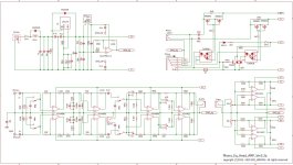
Should R33 not be deleted?
The bottom part has a gain of -1.
If you delete R33, the top will have a gain of +1.
I guess that's what you want.
Also R6 doesn't do anything and can be deleted.
Jan
The bottom part has a gain of -1.
If you delete R33, the top will have a gain of +1.
I guess that's what you want.
Also R6 doesn't do anything and can be deleted.
Jan
Last edited:
Dear Mr. Jan Didden,
Thank you very much for your advice! I am truly grateful.
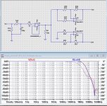
If R33 is not included, the feedback level will vary between the HOT and COLD sides, resulting in a phase shift in the high-frequency characteristics.
I am attaching the simulation results.
The purpose of this circuit design was to align the phase characteristics by maintaining the same feedback level.
As you rightly mentioned, removing R6 should not pose any issues. Thank you very much!
Yours Truly
ERI
P.S
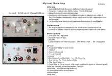
I would like to add the following. This circuit can easily switch between an inverting amplifier and a non-inverting amplifier using terminal toggle switches, which is very convenient.”
Thank you very much for your advice! I am truly grateful.
If R33 is not included, the feedback level will vary between the HOT and COLD sides, resulting in a phase shift in the high-frequency characteristics.
I am attaching the simulation results.
The purpose of this circuit design was to align the phase characteristics by maintaining the same feedback level.
As you rightly mentioned, removing R6 should not pose any issues. Thank you very much!
Yours Truly
ERI
P.S
I would like to add the following. This circuit can easily switch between an inverting amplifier and a non-inverting amplifier using terminal toggle switches, which is very convenient.”
Attachments
Last edited:
Excellent! I learned something today. Well done.
One more question: that R33 does lower loop gain, so I would expect the top circuit to have higher distortion than the bottom circuit.
What is your opinion about that? Did you measure that?
Jan
One more question: that R33 does lower loop gain, so I would expect the top circuit to have higher distortion than the bottom circuit.
What is your opinion about that? Did you measure that?
Jan
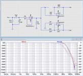
Thank you for sharing your perspective. We hadn’t considered comparing distortions, so I conducted a simple simulation. I will upload the results for your reference. It appears that Both the HOT side and the COLD side appear to have nearly identical characteristics.Excellent! I learned something today. Well done.
One more question: that R33 does lower loop gain, so I would expect the top circuit to have higher distortion than the bottom circuit.
What is your opinion about that? Did you measure that?
Jan
Best regards.
ERI
LTspice is not very good for distortion - it is, but you never know how well the models are for non-linearity.
It would be better if you could measure, but that requires instruments. But it should be good enough.
Jan
It would be better if you could measure, but that requires instruments. But it should be good enough.
Jan
Thank you, JAN. It took me a while to recall how to use LT-SPICE since it’s been a while. I will upload the THD calculation results.
Best regards.


Best regards.
- Home
- Amplifiers
- Headphone Systems
- BTL for my headhone Amp