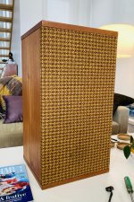
I'm helping my father revive some old cabinets my grandfather had made for speakers in Hobart, Tasmania, circa 1960-something. He's kept them for all these years and we just pulled them out of storage. The timber (teak) is in beautiful shape as are the front grills - I love the retro look. The drivers however are beyond saving. The timber for the baffle will be replaced to suit the replacement drivers.
I've built Frugel Horn mk3's to date but this is my first attempt at a multi-way speaker. The front baffle is 330x610mm, tweeter is an SBA SB29RDC-C000-4 and woofer is an SBA SB23NBACS45-4. Enclosure volume is ~41L once the drivers are in there.
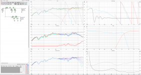
I've simulated the Baffle and enclosure and am fairly happy with where I've got to so far - my concern however is the roll off from ~300Hz. The speakers will be in corners so I expect there to be some room gain... Anything I try only results in the low end dropping or the mid-high dropping, requiring much more power (the amp to be used is fairly low powered). Without fully understanding enclosure effects, my hope is that the total SPL increase indicated in the enclosure chart from 300-50Hz will compensate, but again, this is a gap in my knowledge.
What can I do about this? Additional comments on impedance and phase are welcome too. Target XO is 1750Hz 🙂
I've built Frugel Horn mk3's to date but this is my first attempt at a multi-way speaker. The front baffle is 330x610mm, tweeter is an SBA SB29RDC-C000-4 and woofer is an SBA SB23NBACS45-4. Enclosure volume is ~41L once the drivers are in there.
I've simulated the Baffle and enclosure and am fairly happy with where I've got to so far - my concern however is the roll off from ~300Hz. The speakers will be in corners so I expect there to be some room gain... Anything I try only results in the low end dropping or the mid-high dropping, requiring much more power (the amp to be used is fairly low powered). Without fully understanding enclosure effects, my hope is that the total SPL increase indicated in the enclosure chart from 300-50Hz will compensate, but again, this is a gap in my knowledge.
What can I do about this? Additional comments on impedance and phase are welcome too. Target XO is 1750Hz 🙂
Attachments
Last edited:

You use a 4th order electrical on midwoofer and tweeter,
see if you can get away with 2nd order electrical on both.
Saves on XO components and complexity.
see if you can get away with 2nd order electrical on both.
Saves on XO components and complexity.
No pictures of the speaker?
Attached 🙂
You use a 4th order electrical on midwoofer and tweeter,
see if you can get away with 2nd order electrical on both.
Saves on XO components and complexity.
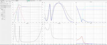
Hmm, I played around with 2nd but struggled to get everything under control... Best I can do is a 3rd order (attached). Is the impedance drop to ~2.5ohms acceptable for a low output amp?
Attachments
2.5ohms is too low, not many amplifiers can handle that.
You have too much overlap between woofer and tweeter.
The minimum impedance of the woofer is about 4 ohm, that should also be the minimum impedance of your design.
Are your simulations based on actual measurements of your drivers in your cabinets ?
If not, you really can't trust your simulations for 100%
See here for 2nd order on SB23NBACS45-8
With your 4 ohm you can halve the coil induction and double the capacitor uF of the 2nd order filter.
Last edited:
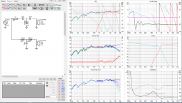
Something looks wrong. It may be best to explain the process you went through to get those measurements. If your measurements are wrong, your simulations are wrong and you'll be wasting your time.
Measurements were done by simulating the front baffle using VituixCAD. Of course, putting the drivers in and measuring them would be ideal but I am still in a pure learning phase - as a visual learner it would be very useful for me to simulate, build, then test, and understand the real world implications of that process and define the gap between simulation and reality.
If however this is considered a complete waste of time I’m certainly willing to go ahead and get the drivers, do measurements and go from there 🙂
If however this is considered a complete waste of time I’m certainly willing to go ahead and get the drivers, do measurements and go from there 🙂
Not at all. I hear you want to balance the lower hundreds. With what information there is, try pulling down the mids and highs. You seemed to be deliberating over that but it may be something you need to do.
Looking at the datasheet, your mids (500hz to 700hz) should to be level with the frequency response at 200hz. Ignore the bump at 330hz for now. It may not be audible.
The S23 is a 90dB sensitive woofer. Your target sensitivity should be ~85 - 87dB depending on how much bafflestep you need (size), front wall / corner placement and your bass preferences.
Forget optimising the tweeter network until you get the bass / bafflestep compensation right. otherwise you'll be redoing the tweeter.
Having a 93dB sensitive tweeter - means you'll need an L-Pad or series resistor depending on phase behaviour to attenuate the tweeter.
The S23 has quite a bit of off-axis rolloff, so 2KHz is probably your upper limit for semi reasonable off-axis behaviour
Increase the value of the tweeter inductor and reduce the capacitors. may increase the impedance without compromising slope. Phase (response shaping) trick - Use a small value resistor in-series with the tweeter inductor to align phase (or in series on the woofer capacitor)
Edit: I see your crossover in post #6 addresses BSC via the filter slope (~6dB).
I still think the tweeter is too hot.
I still think the tweeter is too hot.
You use a 4th order electrical on midwoofer and tweeter,
see if you can get away with 2nd order electrical on both.
Saves on XO components and complexity.
I beleive it can not be cuted-off with a LR12 as high, I planned mine around 550 hz LR12 at max, I would have liked more 700 or 800 hz but too much distorss (H5 around 1200 and H3 below 2000 hz ask stiffer cut-offs). LR24 below 1K hz imho. The sb23 is more a bass than a mid...
Last edited:
- Home
- Loudspeakers
- Multi-Way
- BSC.... the final... Step! Am I almost there?