Hi,
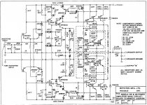
I own a rather old 3B Bryston ( 1979 model ) with a blown channel a few years ago ( there was an older post of mine those days ). I've tried to replace all the elements of the pcb ( matched transistors, resistors, high quality capacitors etc ) and today I've tried to power it up. After some difficulties with the drivers transistors ( MJE15030/15031 ) and with the in series bulb voltage limiter I've managed to make it work without blowing any fuses but I'm having a problem with the DC Bias. No matter what I do, it starts from 50mV and falls to -30mV and dropping. It won't stabilise. I am attaching the schematics to give me some advise. I've followed the schematic perfectly except the 22pF caps that I saw in earlier versions that were 10pF being used and tried then on ( would this cause any problem? )
Thanks in advance.
Attachments
Hi Guys
If the bias pot is set for lowest current initially, then the output stage should be cold at start-up. Either the diode or the BJT of the bias generator will be mounted on the heat sink. An idle current per device of about 60-70mA is typical. You have to attach your meter leads to one of the emitter resistors using alligator clips, then move the bias trim very slowly to move towards the calculated voltage drop. 60mA through 150mR produces 9mVdc.
Are you reading 50mV across one of the Re's? That would be 333mA per output string - way too high!
In later models Re was changed to other values, but so too were the output devices to much faster ones.
What are all the hatch marks? Did you remove all the compensation caps? Replace them? The amp will oscillate (likely) without them.
Bryston closely matches the devices in complementary positions, and in related circuits such as the diff amps. using unmatched devices will make the best-case THD quite a bit higher and there could be DC offset.
Bryston has a strong service support ethic and will help you with this amp.
Have fun
Kevin O'Connor
I have downloaded the service info from the site and followed the bias settings instructions. I have shorted the input ( positive to ground ) and put my voltmeter leads to the output terminals. There is a test pot above a Re of a 6609, if I remember correct it gives about 50mA, I will check on it again later.
Don't mind the hatch marks, i have downloaded the image. As I mentioned earlier, the only difference is that I've changed the 22pF value to 10pF. Would that be a problem?
I think I've managed to match the transistors, I used a transistor tester and tried to keep all of the ratings to the optimal of each type. Of course, as I saw, it's not possible to match the beta's of each type of transistors ( e.g. to match all the pnp's, to match all the npn's to the same value ), after all, if that was possible, the would be just one set of transistors, and not the 5550/5400 - 5210/5087, correct? I also tried to even match the resistors values to 0.1% - 0.2% of the values of the schematic, the caps are matched to 0.1-0.5% as well.
Last edited:
P.S. I already have two brand new pcb's ready to attach and get it work, but I want to fix my old ones ( it's a matter of honor ) and besides that, to use the high quality elements I bought ( roe / ero caps, vishay resistors etc ).
Hi Guys
Your first post says the bias starts at 50mV and drops to -30mV suggesting the meter reading goes negative, in turn suggesting that the idle current has changed direction - which it cannot do.
When you say "bias" do mean the DC offset voltage at the amplifier output? That can change direction. Newer models have an offset trimpot and a bias pot; this older version has just the bias pot for the output stage.
Have fun
Kevin O'Connor
Yes, i was trying to measure at the amplifier output but I found out about the test spot located above an emitor resistor. I gave it a try, but it needs a professional since I haven't got the appropriate equipment ( dummy load, osciloscope ). So, I gave up, although this circuit looks easy, it's not an easy stuff for an amateur, no matter how much I would enjoy the procedure or repairing it.
Thanks for you time fellows!
Thanks for you time fellows!
- Status
- Not open for further replies.
- Home
- Amplifiers
- Solid State
- Bryston 3B Restoration problems