Perry and any other of the Guru's here. Can you help me with some parts identifications and any other suggestions to go along with repairing this amp please.
R62 - ?
Q7 - C3228
Q8 - A1275
R61 - ?
R62A - ?
C219D - ?
R61A - ?
Q8A - A1275
Q7A - C3228
I also decided to replace all the DNP outputs and all the IRF's.
Are there any other suggestions as to anything else that may have shorted, opened or create issues. Thanks for the help..
R62 - ?
Q7 - C3228
Q8 - A1275
R61 - ?
R62A - ?
C219D - ?
R61A - ?
Q8A - A1275
Q7A - C3228
I also decided to replace all the DNP outputs and all the IRF's.
Are there any other suggestions as to anything else that may have shorted, opened or create issues. Thanks for the help..
I don't have anything on that amp specifically but it's likely similar to the other amps.
R61/61a = 470
R62/62a = 3.3k
C219D = 1uF 5% 100v
R61/61a = 470
R62/62a = 3.3k
C219D = 1uF 5% 100v
OK, Perry I am stumped here.
I replaced all my IRF064's (fets) and decided to bench test the amp without the output transistors (DPN's) in it. The amp kicked on,, relay engaged and draws about 1-2 amps of current. So I decided to install the output transistors. Once I turn it on, it immediately draws about 20amps of current and the output transistors get very hot. Have to shut it down almost immediately to prevent burning it up. Any ideas as to what could be the cause? Forgot to mention it is a BXI2408 Brutus.
Any help would be appreciated. Thanks
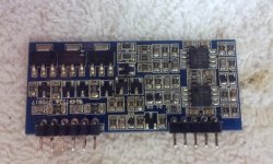
Post a photo of the audio driver board in the amp.
What is the exact part number on the output transistors?
What is the exact part number on the output transistors?
Ok, Here is what I found so far:
Q226 was open, so I had to replace it.
The output transistors are: DFP70N06.
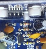
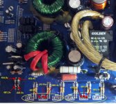
What has me puzzled is the on Q288 I have -081.5 vcc's on the two outer legs and +14.45 volts on the middle. ( see pics). I pulled the resistor also to see where it was coming from.
Also on the output transistors i have negative voltage on the 2 outer legs. ( I ended pulling out all the outputs to troubleshoot the amp.)
Forgot to say that I tested the 2 transistors on the audio board and they were good. Seems to be the issue in some cases, but I dont think it is in this one.
Q226 was open, so I had to replace it.
The output transistors are: DFP70N06.
What has me puzzled is the on Q288 I have -081.5 vcc's on the two outer legs and +14.45 volts on the middle. ( see pics). I pulled the resistor also to see where it was coming from.
Also on the output transistors i have negative voltage on the 2 outer legs. ( I ended pulling out all the outputs to troubleshoot the amp.)
Forgot to say that I tested the 2 transistors on the audio board and they were good. Seems to be the issue in some cases, but I dont think it is in this one.
Attachments

Last edited:
Why does the voltage on Q288 concern you? It seems to be about right.
Half of the outputs are supposed to have negative rail on their gate and source legs. In operation, the gate leg of those outputs will have approximately 5v over the negative rail voltage.
Were any of the output transistors defective when you checked them out of the board?
Half of the outputs are supposed to have negative rail on their gate and source legs. In operation, the gate leg of those outputs will have approximately 5v over the negative rail voltage.
Were any of the output transistors defective when you checked them out of the board?
I'd accuse your meter of taking inconsistent readings, or you, or both. And you didn't use the 'm' in millivolt (mv, not v). Unless you really think you have 104 volts there..
Maybe you should take them again and post the correct voltage scales. That would be helpful and appreciated.
Maybe you should take them again and post the correct voltage scales. That would be helpful and appreciated.
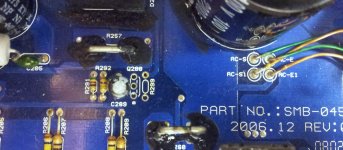
The 104v may be OK if the voltage on the other end of that diode (D21) is positive instead of negative. The higher-than-rail voltage is the supply voltage feeding the drivers standing in front of the audio driver board.
I wouldn't expect to see the -10v on the output transistors but I don't think it indicative of any serious problem.
I wouldn't expect to see the -10v on the output transistors but I don't think it indicative of any serious problem.
That was my error. It is positive. Just looked at the picture and noticed I typed wrong. It is 081.9 on the other end of the diode, so I guess its ok.
The -10V on the output is where I may have the problem.I went a head and installed the outputs on the negative voltage sides of the board, and the amp will turn on and relay engages with about 2 amps of current draw.
But once I installed the outputs on the positive side. It immediately draws over 20 amps once I apply Vcc and the outputs gets very hot.
Dont know the cause. Wanted to ask and reverify. Would R61/61a have anything to do with it, and are the values 470 ohms?
I tried it both ways. But I have come a long way now.
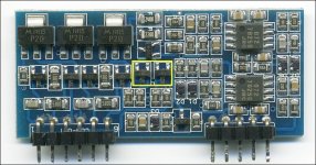
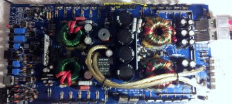
I pulled the power and driver boards off another amp. Guaranteed working. But what happens now is when i apply Vcc to the amp it powers on ok, but within seconds starts to draw high current and burns up one DFP70N06 Mosfet. That one fet gets finger burning hot. I posted a picture for you. I have checked and double checked all I could. Any ideas?
I pulled the power and driver boards off another amp. Guaranteed working. But what happens now is when i apply Vcc to the amp it powers on ok, but within seconds starts to draw high current and burns up one DFP70N06 Mosfet. That one fet gets finger burning hot. I posted a picture for you. I have checked and double checked all I could. Any ideas?
Attachments
That would tend to indicate that the gate resistor is out of tolerance for that FET.
This amp has the same board as the BXI2006.
This amp has the same board as the BXI2006.
Nice catch Tim. I blew it up and they're not burned. Those are NOS resistors from long ago, seen them many times in old jukebox amplifiers. I'd lean toward a broken pad on the FET side of the resistor.
The drivers are new and the resistors are also. Now I am second guessing myself all over again. Maybe I need some expertise here. The amp was in pieces when got it. All the fets and output transistors were taken out and were in a plastic container. So I decide to replace them all. The amp uses 12 IFR640's and 12 DFP70N06.
My question is which ones would be the power fets and which would be the outputs. Maybe I installed them incorrectly, but I have gone over this amp with a fine tooth comb and cant find anything else wrong. Currently I have the irf640 as the outputs.
What do you guys think?
My question is which ones would be the power fets and which would be the outputs. Maybe I installed them incorrectly, but I have gone over this amp with a fine tooth comb and cant find anything else wrong. Currently I have the irf640 as the outputs.
What do you guys think?
- Status
- Not open for further replies.
- Home
- General Interest
- Car Audio
- Brutus 2408D part identification: