And....... success!!
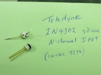
Good news! I managed to get some of the old Teledyne 2N4302 FET’s from a guy in the UK ( silicon-ark.co.uk ), who was actually a really good guy and great to deal with. The parts were here within a week with standard airmail.
So, I had a small amount of time spare the other night so carefully removed the old Teledyne FET, and installed the new one carefully using a fairly pointed soldering iron and heat sinks and tweezers as required to get it into place. (Just copied the same leg layout as the old FET, but did leave the legs slightly longer to provide a little more room to work, etc.
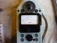
Tested the unit and it powered up, but when I switched the meter to ‘impulse’ or peak function the needle slowly rose up to about the ‘0’ mark on the meter scale (which is actually about 25% deflection from the left (infinity), as the scale goes -10, 0, +10db) and sat there. When pressing reset button it wouldn’t drop back to infinity where it was supposed to come to ‘rest’ after pressing the button. About this stage I am thinking "ok, what have I stuffed up now?" Had I got the leads on the FET wrong?
Anyway, so I did a simple clap test and found that the needle deflected and then held perfectly (no falling back slowly like it was doing previously). Clap louder – more deflection then still holds well. Pressing reset button allowed the needle to drop back to ‘0’ again, but not infinity (hard to the left). So about this stage (it was very late at night) I figured that the FET leads must be right, but there must be some simple adjustment to correct the needle position. Looking at the service book info I figured it would most likely be potentiometer P601, and sure enough that was it. Turning the adjustment clockwise increased the needle position. Adjusting the potentiometer back (in the end about 90-degrees anticlockwise from previous position) corrected the position of the needle to where it should be – but I found I had to press the reset button in order to get the needle to fall back down. So after a bit of mucking around I got it all working perfectly – as far as I can tell – but I will have to run some tests on it simultaneously alongside another meter just to check that all of the responses for the peak holds are the same. If it passes basic testing then it will go to the lab for proper calibration check.
I will attach some more pics and info on parts, just in case someone has the same fault to correct. Going by the process and info already in this thread i would suggest checking things as follows:
1. Check the reset switch is ok and not leaking across the contacts.
2. Check the Capacitor C604 on meter circuit. (temporarily substitute with another similar cap for testing purposes.
3. Check 'diode' Q601 (the obsolete SF115 or SF115A) for leakage by disconnecting one end once a charge has been applied to the cap to cause the meter to deflect on peak hold (clap test on the 120db setting should work ok for this purpose.)
4. Replace the FET (V604), which may be either the older style E102, or later 2N4302. (or a 2N3819E might also work?? Mooly?)
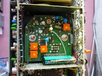
In the pics attached P601 is the one just to the side of the 2N4302 FET. You can see the black pen mark showing the original setting, and the final adjusted/corrected setting about 90-degrees anti-clockwise. Some info on the SF115A diode is all i could find, but there may be something else online that you might find, if necessary.
A guy on Ebay from Italy seems to have some of the original ERO-Roederstein caps (for C604), as well as some of the other old style caps ('tropical fish') that are located on the power supply circuit board (C909,C914,C916) that on both of the meters i have viewed showed some heat damage and cracking, all of which i have replaced as a precaution. I don't know if these old striped original caps are any better than more modern similar replacements? Maybe someone on here will know? I just thought i would share what info i have found.
Many thanks again to all those who have helped out on this thread, hopefully it will be of use for reference purposes to others in the future. Or if you get stuck for parts, send me a message (or email). I have some spares if required.
Thanks, Dean.
Good news! I managed to get some of the old Teledyne 2N4302 FET’s from a guy in the UK ( silicon-ark.co.uk ), who was actually a really good guy and great to deal with. The parts were here within a week with standard airmail.
So, I had a small amount of time spare the other night so carefully removed the old Teledyne FET, and installed the new one carefully using a fairly pointed soldering iron and heat sinks and tweezers as required to get it into place. (Just copied the same leg layout as the old FET, but did leave the legs slightly longer to provide a little more room to work, etc.
Tested the unit and it powered up, but when I switched the meter to ‘impulse’ or peak function the needle slowly rose up to about the ‘0’ mark on the meter scale (which is actually about 25% deflection from the left (infinity), as the scale goes -10, 0, +10db) and sat there. When pressing reset button it wouldn’t drop back to infinity where it was supposed to come to ‘rest’ after pressing the button. About this stage I am thinking "ok, what have I stuffed up now?" Had I got the leads on the FET wrong?
Anyway, so I did a simple clap test and found that the needle deflected and then held perfectly (no falling back slowly like it was doing previously). Clap louder – more deflection then still holds well. Pressing reset button allowed the needle to drop back to ‘0’ again, but not infinity (hard to the left). So about this stage (it was very late at night) I figured that the FET leads must be right, but there must be some simple adjustment to correct the needle position. Looking at the service book info I figured it would most likely be potentiometer P601, and sure enough that was it. Turning the adjustment clockwise increased the needle position. Adjusting the potentiometer back (in the end about 90-degrees anticlockwise from previous position) corrected the position of the needle to where it should be – but I found I had to press the reset button in order to get the needle to fall back down. So after a bit of mucking around I got it all working perfectly – as far as I can tell – but I will have to run some tests on it simultaneously alongside another meter just to check that all of the responses for the peak holds are the same. If it passes basic testing then it will go to the lab for proper calibration check.
I will attach some more pics and info on parts, just in case someone has the same fault to correct. Going by the process and info already in this thread i would suggest checking things as follows:
1. Check the reset switch is ok and not leaking across the contacts.
2. Check the Capacitor C604 on meter circuit. (temporarily substitute with another similar cap for testing purposes.
3. Check 'diode' Q601 (the obsolete SF115 or SF115A) for leakage by disconnecting one end once a charge has been applied to the cap to cause the meter to deflect on peak hold (clap test on the 120db setting should work ok for this purpose.)
4. Replace the FET (V604), which may be either the older style E102, or later 2N4302. (or a 2N3819E might also work?? Mooly?)
In the pics attached P601 is the one just to the side of the 2N4302 FET. You can see the black pen mark showing the original setting, and the final adjusted/corrected setting about 90-degrees anti-clockwise. Some info on the SF115A diode is all i could find, but there may be something else online that you might find, if necessary.
A guy on Ebay from Italy seems to have some of the original ERO-Roederstein caps (for C604), as well as some of the other old style caps ('tropical fish') that are located on the power supply circuit board (C909,C914,C916) that on both of the meters i have viewed showed some heat damage and cracking, all of which i have replaced as a precaution. I don't know if these old striped original caps are any better than more modern similar replacements? Maybe someone on here will know? I just thought i would share what info i have found.
Many thanks again to all those who have helped out on this thread, hopefully it will be of use for reference purposes to others in the future. Or if you get stuck for parts, send me a message (or email). I have some spares if required.
Thanks, Dean.
Attachments


Great to hear you have it all working now... it was an interesting problem in that it had to be a microscope leakage that was pulling the cap voltage down. That really only left atmospheric/contamination/pollution, a leaky cap, a leaky diode, a leaky switch or a leaky FET 🙂 and of course it had to be the oddball part.
I'm pretty sure a generic FET like a 2N3819 or similar would be able to work OK as the bias trim preset seems to have a fairly wide range of adjustment.
Now you know the circuit works correctly you can always try different caps and see which hold the charge best (lowest internal self discharge).
Good result all in all