Merlin really appreciate you helping me out. Wm8741 out put about 2v , with a x2.8 gain it will overload my integrated amp, I guess?
Ballpencil suggested to go with just BCF in an earlier post to avoid it. What is a tube effect box?
That is my integrated amp and it's maximum sensitivity is 3v
http://www.simaudio.com/DATA/PRODUIT/58_en_detail~v~integrated-amplifier.pdf
Ballpencil suggested to go with just BCF in an earlier post to avoid it. What is a tube effect box?
That is my integrated amp and it's maximum sensitivity is 3v
http://www.simaudio.com/DATA/PRODUIT/58_en_detail~v~integrated-amplifier.pdf
Last edited:
Yes, perhaps you should stick with that for now, and worry about "tube sound" afterwards.Ballpencil suggested to go with just BCF in an earlier post to avoid it.
A line stage or something that serves little purpose other than to add some tube magic. Not required, not 'purist hi-fi', but gratuitous fun.What is a tube effect box?
the second part of unbalancer is actually BCF. So is it practical to get the board of Unbalancer and just use the second part which is BCF by bypassing the initial gain stage?
In that way I can use Unbalancer for current output DACs as I/V stage. What do you guys think about that?
In that way I can use Unbalancer for current output DACs as I/V stage. What do you guys think about that?
If you don't mind the unused PCB space then sure, knock yourself out.the second part of unbalancer is actually BCF. So is it practical to get the board of Unbalancer and just use the second part which is BCF by bypassing the initial gain stage?
One board and make it work for both i-out and v-out DAC? Are you then going to put all three circuits (unbalancer and both DACs) in one enclosure? If that is not your plan, it should be. At least for the i-out DAC and Unbalancer since i-out works with such low current, it won't like having to travel long wires and interconnect before arriving at the v-i resistor.
I stand by my suggestion: v out DAC and BCF in one enclosure and if you have i out DAC, build the unbalancer for it and put in one enclosure as well.
I stand by my suggestion: v out DAC and BCF in one enclosure and if you have i out DAC, build the unbalancer for it and put in one enclosure as well.
I stand by my suggestion: v out DAC and BCF in one enclosure and if you have i out DAC, build the unbalancer for it and put in one enclosure as well.
I too think so.
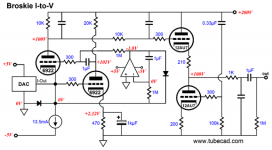
There is a better IV converter from Broskie mentioned here.
Broskie I-to-V
Don't think he made a board for it .
At least in his description it seems better than just using a resistor as IV convertor followed by amplifying the voltage.
With a differential current-out DAC like the PCM1795 or PCM1798, we face the problem of the DC offset. The DAC expects to see 0Vdc and 0-ohms at its two outputs. In addition, the DAC draws an idle current of 3.5mA through its outputs.
(This make using two load resistors problematic, as a pair of 100-ohm I-to-V resistors will each create a 0.35Vdc offset. At its peak current swing, the DAC will draw about 5.5mA, which against a 100-ohm resistor will equal 0.2Vpk of AC signal and 0.55Vdc of peak DC voltage; this may be far too much for the DAC to function. I have found from past experiments that about 60 ohms is high as I dare go with a current-out DAC, otherwise the dreaded, sleepy, slew-limited sound results.)
Attachments
One of the way to make CCS is to use LM317 with current adjust resistor between OUT and ADJ legs. 13.5mA requires that resistor to be 92.59 ohm which can only bought at an imaginary parts store. Hence, swap the resistor with multiturn trimpot (200 ohm should be OK) and adjust trimpot for the DAC output to be as close as possible to 0mV when there is no signal (idle)
LM317 / LM338 / LM350 Current Regulator Calculator and Circuits
LM317 / LM338 / LM350 Current Regulator Calculator and Circuits
more questions
back with more questions.
what should be the value of R1,R2 ,R4 and R5?
BCF data sheet says 10k to 100K and in paranethesis 47k for 6DJ8.
back with more questions.
what should be the value of R1,R2 ,R4 and R5?
BCF data sheet says 10k to 100K and in paranethesis 47k for 6DJ8.
Attachments
Last edited:
Also the value of C3,C4 which is mentioned as 1uk/16v and
1kμF in a different part (last page ) of manual.
http://glass-ware.com/User_Guides/BCF%209-Pin.pdf
I just found out a C7 and C8 which are not mentioned anywhere in manaul. near the top of the board ( small electrolytic cap footprint)
1kμF in a different part (last page ) of manual.
http://glass-ware.com/User_Guides/BCF%209-Pin.pdf
I just found out a C7 and C8 which are not mentioned anywhere in manaul. near the top of the board ( small electrolytic cap footprint)
Last edited:
R1, R2 should be as high as possible to obtain the highest input impedance (to unburden the preceding stage) but not too high that it makes a low pass filter with the tube's Miller capacitance and cutoff high audio frequencies. 47k is a good compromise, try with that first.
1kuF is just the typical 1,000uF.
C7,C8 is not really necessary. In fact, DO NOT use them if you are using AC source for heater power. They are just smoothing caps for if you use DC. Values 47-470uF should be fine.
1kuF is just the typical 1,000uF.
C7,C8 is not really necessary. In fact, DO NOT use them if you are using AC source for heater power. They are just smoothing caps for if you use DC. Values 47-470uF should be fine.
Great help ballpencil,appreciate it. I was just making sure it is not a typo with cap value for C3 and C4 and it is not 1 uF.
Hi Kinku
I want to do a diy build of the Broskie cathode follower as well (the full kit version is out of my price range for now) but it (to me) looks pretty complicated so congratulations on what you have achieved so far.
Are blank PCB's available or are you building point to point? If you started your build any photo's would be good.
Thanks
Although I have got through most of the tutorial in the valvewizard pdf as mentioned earlier in this thread, I admit to being still unsure of my abilitiy to understand enough on what's required to build the Broskie Cathode Follower.
Kinku is using the ECC88 / 6DJ8 tubes - I know its unlikely that I will have enough knowledge to contribute to this thread, so I hope to use the same tubes and components to build my BCF.
Thank-you Kinku for doing all the hard work and the other members that have contributed so far.
Kinku is using the ECC88 / 6DJ8 tubes - I know its unlikely that I will have enough knowledge to contribute to this thread, so I hope to use the same tubes and components to build my BCF.
Thank-you Kinku for doing all the hard work and the other members that have contributed so far.
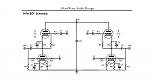
An unbalancer can be done with a signal transformer !
No power used, no tubes ( or transistors)involved, no triming and no fuzz.
No power used, no tubes ( or transistors)involved, no triming and no fuzz.
I think for the AK4396,
Input 12au7 Output 6DJ8.
230 - 245 V B+ Passive rectification, SS diodes.
Suggested values, open for revision:
R1 R2, = 10K + // Capacitors
R3 R4 = 330
R6 (LM334), =7R
R7, R8, = 24K
R9,R10,R11, R12, = 10k to 07K , uncertain
R13, R14, = 150 to 250, uncertain,
R15 1M
C5 and C6 filters around 50pf to 60pf
C15, C17 = 0.2uf to revise
C3= 3uf, preliminary
One big question is why not bypass the Rk of the unbalancer?
One big question is why not bypass the Rk of the unbalancer?
This typology already has a low output impedance, a bypass C will lower it more, but it will not apply any gain, but a greater distortion.
This typology already has a low output impedance, a bypass C will lower it more, but it will not apply any gain, but a greater distortion.
I tried with bypass and no bypass.
The balance of voltage is not perfect for some reason.
Maybe the 20K and 20.75 K resistors that I choose changes the balance through feedback level of the input grid.
But the THD is very low with and without the bypass.
It makes more a difference at higher frequencies, but not much.
This is preliminary, but even with this low THD the broskie sounds totally different than a pure single end cathode follower tube.
It is not mellow and soft, the sound is more mature.
It sounds way less digital than OPAMPS.
It sounds maybe more natural than my high feedback discrete transistor output stage in single ended.
However, it is not replacing my vinyl. Only 1/3 there in terms of quality.
- Status
- Not open for further replies.
- Home
- Amplifiers
- Tubes / Valves
- Broskie unbalancer and Aikido Help