Hi,
I am trying to make an unbalancer for my system. I have read the manual http://glass-ware.com/User_Guides/Unbalancer%209-pin%20-PS.pdf
few times. I do not know anything about tubes and I believe there are many out there in the same boat.
What I am trying to do with this thread is to collect opinion about how to make it with correct parts.
What I understood from reading so far
any transformer with secondary voltage between 180-230Vac can be used to power the tubes and above 300VAC secondary it can be difficult to adjust the voltage with the R12 ?
The manual gives details on current draw and voltage drop that can be achieved to bring the B+ voltage to 240-250,in the last page.
But I honestly could not figure out how to calculate the current to find the value of R12.
There are 'Typical part values' that mentions a B+ voltage in the list for each tube. But is that the maximum voltage that a tube handles or a recommended value or something else?
Also what is the fundamental difference between Aikido and Broskie cathode followers?
I am hoping with this thread we can help a lot of people who wants to try this circuits out ,but struggling to find answers, like myself?
Please avoid discussions on subjective quality of tubes and brands of capacitors etc.
Hope to get some help from masters out there.
First of all, it would be great if you can simply show the schematic here so those who are not familiar with John Broskie's circuit can still help you. Mr.Broskie spills all his bean on the website so i think he wouldn't mind you showing the schematic. You'll get bigger chance for help this way, no? For instance, what is R12? Anyway, i know from clicking your pdf link that it's part of the RC filter on the Power Supply line.
First of all, do you need any gain from the unbalancer? i.e does your source produce enough voltage to be fed to your power amplifier directly? If your source is CD player or digital, most likely you don't need any gain.
You are actually talking about three circuit here, i believe: Unbalancer, Aikido Cathode Follower and Broskie Cathode Follower. In essence, here are the differences:
- Unbalancer = provides gain, balanced input, single-ended output
- Aikido Cathode Follower = no gain, single ended input & output
- Broskie Cathode Follower = no gain, balanced input, single-ended output
If you need any gain, the question becomes more complicated: how much gain do you need? This determines what input tube you need on your unbalancer. Eventually, along with the decision of the output tube, this answers the B+ requirements, current consumption and eventually, R12 value and your transformer.
If i have to offer one solution out of the hundreds of option you can chose, i will assume you actually don't need any gain. Hence you should go with Broskie Cathode Follower as you want to "unbalance". For the tubes, i'd go with 6N23P (said to be equivalent of ECC88/6DJ8) with B+ of 250V. This implies about 120V per tube (5V would be lost per cathode resistor). At 120V, 10mA is a good bias current (to determine this, you need to learn how to draw load lines, valvewizard.co.uk is where i learned).
There you go, per channel, you will be consuming 10mA. So, if your B+ is at 300v and you want to drop it to 250v, you need R12 = 50v/10mA = 5k, i'd go with 4K7/1Watt.
Those are recommended values. You can go deviate a bit but try to aim for these values. Tubes are very tolerant devices. In fact, if not for their high voltage nature, i think they're the best device to learn electronics for new learners as it is less likely to damage tubes than their semiconductor counterpart.But is that the maximum voltage that a tube handles or a recommended value or something else?
I really appreciate your detailed reply. I will post a schematic soon.
The reason why I opted for unbalancer is the possibility bod using it as an IV converter if needed.
Is it possible to use unbalancer without any gain ?
The reason why I opted for unbalancer is the possibility bod using it as an IV converter if needed.
Is it possible to use unbalancer without any gain ?
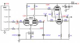
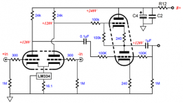
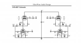
Hi these are the schematics for unbalancer
one with a voltage out DAC and other the original circuit
Link here
The Unbalancer
one with a voltage out DAC and other the original circuit
Link here
The Unbalancer
Attachments
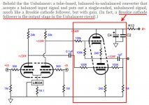
You need to decide what is your primary objective. You mentioned using the unbalancer for an IV converter on post #3 which means you need gain. But then you're showing voltage out DAC on post #4 which to my knowledge outputs high enough line voltage to be fed to power amps directly (depending on the DAC) which means you don't need any gain. Mr.Broskie even mentioned about it here: GlassWare Unbalancer
Fortunately, the last part of your schematic is actually Broskie Unbalancer, which means you can omit the first differential gain stage and connect directly to the Broskie Unbalancer if you don't need any gain.
As shown, it will provide gain. Sure you can introduce negative feedback to reduce gain but it might still give you too much up to a point where you can't turn up your volume control without getting too loud.Is it possible to use unbalancer without any gain ?
Fortunately, the last part of your schematic is actually Broskie Unbalancer, which means you can omit the first differential gain stage and connect directly to the Broskie Unbalancer if you don't need any gain.
Can you please elaborate this. I did not understand,did you mean to say Broskie cathode follower?Fortunately, the last part of your schematic is actually Broskie Unbalancer, which means you can omit the first differential gain stage and connect directly to the Broskie Unbalancer if you don't need any gain.
Did you mean that a part of the picture is a BCF?
So I think there is no option to use unbalancer as both balanced to single ended converter and with modification to an IV stage if needed. Unless I use a feedback to limit gain if I feed the unbalancer from a voltage output DAC( planning to use this Opus - A Balanced DAC ) it will cause issues with high input Voltage gain?
Last edited:
Can you please elaborate this. I did not understand,did you mean to say Broskie cathode follower?
Did you mean that a part of the picture is a BCF?
Yes, sorry.. I meant Broskie Cathode Follower. It says that on the blog. See attached. Have you read all the info on his blog? He will give you application samples and explain how they work.
The only issue you will have if you feed the Opus output to the Unbalancer is you might end up with too much gain which would annoy you from having so little "play" on the volume control. Imagine turning your volume down 100% then turning it up just a tad would get you too loud. This also depends on your Power Amp's sensitivity of course (what is the required input voltage level to produce the rated power output).So I think there is no option to use unbalancer as both balanced to single ended converter and with modification to an IV stage if needed. Unless I use a feedback to limit gain if I feed the unbalancer from a voltage output DAC( planning to use this Opus - A Balanced DAC ) it will cause issues with high input Voltage gain?
So, sure you still have the option to use the unbalancer as IV stage but if you use it for that Opus DAC, it might give too much gain as mentioned. I suggest go ahead build the Unbalancer and use it on your Opus DAC. If you end up having too much gain, all the more fun of minor desoldering to convert the Unbalancer to Broskie Cathode Follower.
A better solution for me would be Opus DAC + Broskie CF in one enclosure. If you then have another balanced DAC with I-out, then build an Unbalancer as IV converter and put them together in another enclosure. That way, you will end up with the more "traditional" approach which is to have all your sources provide line level voltage before proceeding to the next stage (which could be an input selector, a buffer, attenuator (volume control) or directly to an integrated amplifier). Again, this is my preferred way. You might have different idea/system.
Attachments
Thank you so much Ballpencil. I think I will proceed with BCF first and opus and see how things are.
I could not find the details/ article in valvawizard.co.uk. There is so much material in there got lost. Can you please post the links of relevant articles to read ?
I could not find the details/ article in valvawizard.co.uk. There is so much material in there got lost. Can you please post the links of relevant articles to read ?
Start here:
The Valve Wizard
There is a pdf link there.
Happy reading!
Author of that website lurks this forum also by the name merlinb
The Valve Wizard
There is a pdf link there.
Happy reading!
Author of that website lurks this forum also by the name merlinb
Some breakthrough
After reading through the pages in pdf at Valve wizard ,things are slowly started making sense to me.
So I have decided to go with Broskie cathode follower .
I have some 6DJ8 tubes handy so trying to build circuit around it.
B+ Voltage 220 ,which will be divided between two 6DJ8.
Now to find the value of Rk or (R3 and R6) in BCF manual
Will aim for a quiescent current of half, Iq= 7-7.5mA
So the value
Iq = B+/2(rp + [mu + 1]Rk)
7=220/2(2900+[33+1]Rk)
Rk=380 closest 383R (BASED ON AVAILABAILITY AT MOUSER )
Ballpencil does it look ok?
After reading through the pages in pdf at Valve wizard ,things are slowly started making sense to me.
So I have decided to go with Broskie cathode follower .
I have some 6DJ8 tubes handy so trying to build circuit around it.
B+ Voltage 220 ,which will be divided between two 6DJ8.
Now to find the value of Rk or (R3 and R6) in BCF manual
- First draw load line
- Maximum Plate dissipation 1.8W
- Plate Voltage Max 130V
- Plate resistance Rp= mu/gm=33/0.012500= 2640: or using the Average transfer characteristics plot at Iq=7mA;for 150V, Rp= 4000. so for 110V Plate Voltage Rp=110/150 x4000=2900?(not sure if this is correct)
Will aim for a quiescent current of half, Iq= 7-7.5mA
So the value
Iq = B+/2(rp + [mu + 1]Rk)
7=220/2(2900+[33+1]Rk)
Rk=380 closest 383R (BASED ON AVAILABAILITY AT MOUSER )
Ballpencil does it look ok?
Attachments
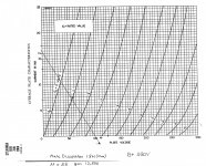
For 6DJ8
- First draw load line
So for B+ VOLT, 220 /2 =110V ,Maximum plate current =16.4mA
- Maximum Plate dissipation 1.8W
- Plate Voltage Max 130V
- Plate resistance Rp= mu/gm=33/0.012500= 2640: or using the Average transfer characteristics plot at Iq=7mA;for 150V, Rp= 4000. so for 110V Plate Voltage Rp=110/150 x4000=2900?(not sure if this is correct)
Will aim for a quiescent current of half, Iq= 7-7.5mA
So the value
Iq = B+/2(rp + [mu + 1]Rk)
7=220/2(2900+[33+1]Rk)
Rk=380 closest 383R (BASED ON AVAILABAILITY AT MOUSER )
Ok plate resistance is defined as change in current for change in plate voltage at a given grid voltage.
rP = ΔVP / ΔIP (Grid voltage maintained constant)
So for the 6DJ8 tube from page 4 of document(or the pic above)
at 50 Vp, Ip is 5.1 mA
at 75 Vp, Ip is 12.5 mA
So rp= 25/ 6.9=3378
Even if you use the new Rp( 3378 in lieu of 2900) Iq is not changing much 🙂.
The load line for each valve in the BCF is actually closer to vertical, because each valves is 'looking into' the low impedance of the other valve, plus the effect of the external load which you don't know.After reading through the pages in pdf at Valve wizard ,things are slowly started making sense to me.
So I have decided to go with Broskie cathode follower .
I have some 6DJ8 tubes handy so trying to build circuit around it.
B+ Voltage 220 ,which will be divided between two 6DJ8.
Whatever the load is, you can assume it is basically a vertical line at B+/2. Therefore, all you need to do is draw a vertical line, choose your quiescent current, and look on the line to find the bias voltage.
Then use Ohm's law:
Rk = Vbias/Iq
Nevertheless, the value you came up with of 390R is fine and will result in about 7mA.
This being the rp?low impedance of the other valve
Also, does the fact that the circuit works in push-pull has something to do with it?
It's less than rp because each valve operates with a large amount of local feedback, which lowers the impedance when 'looking into' it. Being push-pull will make the impedance appear doubled, but it will still be less than rp. For the BCF I expect the figure will be close to 4/gm. But that's not really important. What is important is that you KNOW from the symmetry of the circuit that the quiescent voltage across each valve will be B+/2 (ignoring the small drop across each cathode resistor). So whatever bias you need, it will lie on a vertical line at B+/2.This being the rp?
The load line will then pass through this chosen point and be very steep. So steep that there is not much point trying to draw it.
Last edited:
MerlinB so if that is the case for B+ supply of 220 my load line is a vertical one from 110v and wherever it crosses bias voltage curves?
Sorry confusing to me.
Sorry confusing to me.
Last edited:
Where did you get -1V from?MerlinB so if that is the case for B+ supply of 220 my load line is a vertical one from 110v and wherever it crosses -1v will be the current flow ?close to 25mA
So Rk= 1/0.025= 40ohms. There is something wrong
An externally hosted image should be here but it was not working when we last tested it.
Actually what I said about the load being 4/gm must be wrong, otherwise you'd never get any swing out of it. Duh. But whatever the load is, it will pass through the point on the vertical line.
Last edited:
Thanks Merlin, I changed my previous post after I realized my mistake. So is the tube running in safe zone with this voltage applied and current draw?
Yes, it is dissipating 110V * 7mA = 77 milliwatts, which is not a problem.Thanks Merlin, I changed my previous post after I realized my mistake. So is the tube running in safe zone with this voltage applied and current draw?
Incidentally, I was curious, so I did a SIM of the dynamic load line when driving a 10k external load resistor to clipping. As you can see, it has a slope corresponding to 20 kohms (i.e. it appears doubled in push pull):
An externally hosted image should be here but it was not working when we last tested it.
Last edited:
Heater reference
Thanks Merlin.I really appreciate your input.
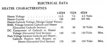
The next hurdle for me is to decide on the voltage divider network for heater voltage reference. Since 6DJ8 has an RMS heater cathode Voltage of 50V max.
With 220V B+ V I am trying to calculate the values for voltage divider network given in BCF data sheet. If I use it the given way, 220V divided between two tubes will be 110. 1/4 of that will be 27.5. Heater to Cathode voltage difference will be 110-27.5= 82.5 which is above the maximum for 6DJ8.
Thanks Merlin.I really appreciate your input.
The next hurdle for me is to decide on the voltage divider network for heater voltage reference. Since 6DJ8 has an RMS heater cathode Voltage of 50V max.
With 220V B+ V I am trying to calculate the values for voltage divider network given in BCF data sheet. If I use it the given way, 220V divided between two tubes will be 110. 1/4 of that will be 27.5. Heater to Cathode voltage difference will be 110-27.5= 82.5 which is above the maximum for 6DJ8.
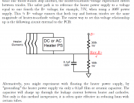
Attachments
That's only for the second triode (pins 6/7/8). The first triode is rated for Vhk=130Vdc or 150Vpk. If you use pins 1/2/3 for the upper triode then you don't need any heater elevation, although you could still add some (ideally less than 50V).Since 6DJ8 has an RMS heater cathode Voltage of 50V max.
Last edited:
- Status
- Not open for further replies.
- Home
- Amplifiers
- Tubes / Valves
- Broskie unbalancer and Aikido Help