Hi,
i've been fiddling around with my T-amp for too long now and i've broken the join on the board to the JK1 negative loudspeaker connector. It's impossible to solder back.
Is there anywhere else on the board i can connect it?
cheers, Tim..
i've been fiddling around with my T-amp for too long now and i've broken the join on the board to the JK1 negative loudspeaker connector. It's impossible to solder back.
Is there anywhere else on the board i can connect it?
cheers, Tim..
audio1st said:Hi Tim,
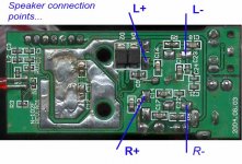
These are my preferred speaker connection points in the attached picture. They are the pins of L3 to L6..
Hope it helps, Barry..
Straight onto the inductors?
That cuts out the entire filter section! Is that a good idea Barry?
Lostcause said:Straight onto the inductors?
That cuts out the entire filter section!
Look again, Lee. 😉 He's just connecting closer to the inductors, that's all. Filter is still inline.
panomaniac said:
Look again, Lee. 😉 He's just connecting closer to the inductors, that's all. Filter is still inline.
These conections are coming straight off the inductors so won't that bypass all the rf filter network after it? C13/14/15/16/17 etc?
Member
Joined 2003
DcibeL said:
Thanks for humouring a novice.....
So it doesn't matter if the decoupling caps and zobel are after the lead-outs as long as they are connecte in some way? I had it in my mind that they had to be in front, exactly like the schematic!
You see, you learn something new every day!
TA
Lee
Hi Lee,
As non of the components are in series between the inductors and speaker outs, then they wont be affected.
If you look at the picture I attached earlier, you will see that the R+ inductor, tracks directly to the the R+ terminal..Then from there it tracks to the filters..
The board is not as neat as the schematic.!!!
I'm new to all this myself and learning as I go. 😉
thanks all for your help. I managed to repair it (just) using the original setup. Will there be any sound difference if i used the original speaker points, but one negative using one of these different points?
I'm completely new to this as you can probably guess!
cheers, Tim
I'm completely new to this as you can probably guess!
cheers, Tim
- Status
- Not open for further replies.
- Home
- Amplifiers
- Class D
- Broken T-amp help!