Hi guys and gals,
I've started my DIY-projector over the week-end and I guess I wasn't delicate enough with it cause the FCC cable broke... damnit!!
But it finally worked, I was able of getting a very nice image on it, while holding this soooo tiny cable with my fingers... but this setup is... unusable 😉
So I'd like tips/hints/advices from all of you DIY-experts on soldering/replacing this important microscopic cable!
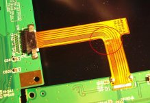
As you can see on the image, on the left side (where the ZIF connector is) there are some "test points" which could be used for soldering. But on the other side, there is no "test points" and neither a ZIF connector, so I'm wondering if that's even feasable/possible to solder?? (Remember, this cable is less than 1cm large and there is like 16 tiny wires in it)
Thank you very much all for your time!
P.S. That would be my replacement part: FFC Extension 16 Pin
I've started my DIY-projector over the week-end and I guess I wasn't delicate enough with it cause the FCC cable broke... damnit!!
But it finally worked, I was able of getting a very nice image on it, while holding this soooo tiny cable with my fingers... but this setup is... unusable 😉
So I'd like tips/hints/advices from all of you DIY-experts on soldering/replacing this important microscopic cable!
As you can see on the image, on the left side (where the ZIF connector is) there are some "test points" which could be used for soldering. But on the other side, there is no "test points" and neither a ZIF connector, so I'm wondering if that's even feasable/possible to solder?? (Remember, this cable is less than 1cm large and there is like 16 tiny wires in it)
Thank you very much all for your time!
P.S. That would be my replacement part: FFC Extension 16 Pin
Attachments
Broken FFC cable
So guys/gals, any tips/hints/advices for soldering this tiny cable??
Thank you all for your time.
highmighty
So guys/gals, any tips/hints/advices for soldering this tiny cable??
Thank you all for your time.
highmighty
There are no "test points" on the other side, but it looks like there is solder to hold the cable (?) or is that just a reflection in the photograph?
There will be, at some point along the circuit trace, a place you can solder to if that is not a soldered connection... use wires instead of a ribbon, and see if it works.
Did I read correctly that this still works if you hold it with your fingers? If so, make up a little tiny clamp and hold it that way.
Thanks Stocker!
Unfortunately the "clamp" option wouldn't work, I've tried it already and it's too unstable, a small movement of the LCD screen and/or OHP would terminate the connection, it won't last more than 1 minute in place 🙁
I will buy an FFC extention cable to replace the broken one, is there any other places around (on the web) where I could buy this part other than lumenlab (6 inches long only)??
Thank you all for your help!!
highmighty @ Montreal, QUEBEC
On my old LCD I resolved a similar situation; I wanted to extend the cable but couldn't find one with the exact number of conductors. I desoldered the cable and threw it away. Then I soldered on an FCC quick-connector and used a longer cable.
cbm5 said:Then I soldered on an FCC quick-connector and used a longer cable.
Can you show me (via a website link maybe) the FFC quick-connector you bought for a better understanding? Are you talking about ZIF connectors on both ends of the cable?
Thanks!
highmighty
Don't know if this is the same site or not but this site has cables and connectors of different pinch sizes, $25 min order or $5 handling fee.
Thanks for the website www.digikey.com, I've checked it out but unfortunately it shows that no FFC cable are in stock 🙁
And how would I know the correct pitch to use? Is 0.5mm a standard in LCD displays?
https://secure.lumenlab.com/shop/product.php?id=18
Thanks!
highmighty
And how would I know the correct pitch to use? Is 0.5mm a standard in LCD displays?
https://secure.lumenlab.com/shop/product.php?id=18
Thanks!
highmighty
Attachments

I managed to extend an FFC by sanding the tracks until the conductor was exposed, then cutting between them with a razor blade. I then soldered the individual tracks to wires.
To be honest you might be off trying to get hold of a new FFC or tracing the tracks back to points on the board like others have suggested.
To be honest you might be off trying to get hold of a new FFC or tracing the tracks back to points on the board like others have suggested.
Hey Highmighty, I picked up a circuit writer pen at Radio Shack might be worth a try . Check the link below.
http://store.caig.com/s.nl;jsession...axePah90n6jAmljGr5XDqQLvpAe?sc=2&category=174
http://store.caig.com/s.nl;jsession...axePah90n6jAmljGr5XDqQLvpAe?sc=2&category=174
Sounds like a real good idea, i'll see if i can find this tool around here.
Thanks a bunch, i'll let u know.
highmighty
Thanks a bunch, i'll let u know.
highmighty
FFC Jumper
The FFC Jumper you need is available at Mouser Electronics.
Find it here FFC Connectors and Cable Jumpers .
The top of the catalog page is connectors, any style will work as long as it has the same number of circuits as your cables. It will be the correct size. Just put the 2 cables face to face (contact to contact) and jam both together into the connector and close the holding mechanism. Sometimes two together just won't fit easily. When that happens, peel off the "stiffener", the small piece of plastic glued on the end of the cable on the opposite side from the bare contacts. That makes the cable just a little bit thinner so that both will fit into the connector.
The bottom of the page has the cable jumpers, in darn near any number of contacts you might need.
The 16 circuit (contact) 6 inch one is only $2.78 and the connector you'll need is only $1.19.
Use professional products and you have a better chance of getting professional results.
That's a very good tip tgreenwood, thanks!
But let me ask you this, what's the difference between FFC connectors of type A and B, which one should I need or is that right that "any style will work"?
Thanks a bunch!
highmighty
But let me ask you this, what's the difference between FFC connectors of type A and B, which one should I need or is that right that "any style will work"?
Thanks a bunch!
highmighty
The difference between A and B is that one has contacts on the bottom inside of the connector and the other has contacts on the top inside of the connector. If we are using them just to hold the ends of two cables together to make it longer, it doesn't matter where the connector contacts are, we are just using it as a precision clamp.
It doesn't look like you can get the type A one from them anyway, I checked and that 16 contact one has been discontinued. If I had to choose between Types B and C, I would get the C because it is a little bit bigger and easier for me to handle. The locking mechanism (they call it an actuator) on B is the kind of little piece of plastic that pulls outward and then pivots up on a little hinge to insert the cable, then you pivot the piece down again and push it in to lock the cable into the connector. I've broken about four of those little hinged b****es and prefer the type C. On type C you pull up on the locking mechanism, insert the cable and push it down again to lock it in.
I haven't tried the low profile ones listed on the right hand side of the page, I have enough trouble handling the regular sized ones.
As far as "any style will work", that is true if you are using it to extend a cable. Remember that it is important to get the matching number of contacts in the connectors because the opening for the cable will be exactly the right width to get everything lined up perfectly.
0.50mm pitch is a standard in LCD displays, but there are always exceptions here and there. For those who don't know, pitch means the distance from the center of one contact to the center of the next contact. The contacts themselves are around 0.35mm wide.
- Status
- Not open for further replies.
- Home
- General Interest
- Everything Else
- The Moving Image
- DIY Projectors
- Broken FCC cable