Hey all,
I was a heavy handed when reconnecting a wire harness, and I damaged the some of the connections on the circuit board (Traces?) I have ample free time right now, so, I'd like to try to fix it.
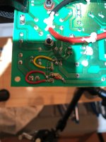
Currently, I have scrapped off some of the resist from the remaining traces, and I've soldered small jumpers from the exposed copper to the original connection.
Still not working. Is there anything I'm not thinking about?
I was a heavy handed when reconnecting a wire harness, and I damaged the some of the connections on the circuit board (Traces?) I have ample free time right now, so, I'd like to try to fix it.
Currently, I have scrapped off some of the resist from the remaining traces, and I've soldered small jumpers from the exposed copper to the original connection.
Still not working. Is there anything I'm not thinking about?
I would clean up the rewiring first. The two red wires look very close to each other at one point, almost shorting. I also don't like the black tipped red jumper cable. The connectors at the ends can go bad.
I would snip off the end of each wire at one end. Strip off the insulation. Bend the wire to the other PCB connection point following the trace path. Solder to the end point. Snip off the extra wire. Check continuity. are connectors P1 and P3 connected to?
There is also a solder joint near the lower right area of the picture that looks questionable. P6?
Copy all that. Yeah, the black tipped red wire thing was just to see what would happen, will replace with out that.
Re: following the trace -- The distance is so small for those two red ones, at this point, is it doing any more real harm to remove more trace to give myself room to work?
I believe that P3 is connected to F2, P6/R26
P1 is connected to D1, F1, D2, R23 and R 25
That that P6 joint is just extra solder from the first draft of the repair. I tried to go from connection to connection, and not along the trace. The factory joint should still be good.
Here is the new without shortening those other wires and following the trace.
Does following the trace make a difference or it is just the CORRECT way of doing it? Basically, if this is good enough, i'd like to just get the thing working, and then I'll go in and make it pretty.
Does following the trace make a difference or it is just the CORRECT way of doing it? Basically, if this is good enough, i'd like to just get the thing working, and then I'll go in and make it pretty.
Attachments

Ahhh, copy that. understood. Everything I had seen was still showing using insulated wire. Good to know for when I make it pretty if need be.
Update, the amp makes noise again. That's good. It sounds very bad though. That's bad.
Cuts in and out, and makes emits a loud high pitched frequency that I'm surprised I can hear. Any advice on how to start trouble shooting what's wrong? Another hint is that if I strum very hard, everything cleans up and holds together.
- Home
- Live Sound
- Instruments and Amps
- Broken circuit board Vox AC4C1