The pins is exacly where to measure. I didn't make my point as well as I thought when saying to the chip. I agree about ground planes. If you need to test a ground plane a hand made board can be OK. I did this on my PSU and got better than the real PCB. To do it make a paper copy, I used insulating tape to mask an area not to be etched. Drill where you need it broken. Do the top surface point to point if you can, I was lucky and could. I didn't used 2 oz copper. I think for want of a cheap metal bar I won't bother.
Another way to test things is a biscuit tin lid. Long before it goes in a case be sure it is happy. The lid to ground will give you a fair idea.
Another way to test things is a biscuit tin lid. Long before it goes in a case be sure it is happy. The lid to ground will give you a fair idea.
Clock speed is a factor but not as much as the signal rise times on the board, as some believe super fast rise times are best (they are not, the correct rise time is) cos they give a nice square edge. The trouble is they add extra HF harmonics that the system then has to deal with, and the faster the rise times the more important correct layout is.....
Is there a way to mimic the X10 probe with it's 10M impedance and get the direct BNC cable connection into the measuring jig?
Most of the differential preamplifiers for small signal measurements that I have seen are 1M input, the same as most scopes.
Here is one of the few having a much higher input impedance. 5186
Much good information. Thanks folks. Need to read up on the EMC book.
I'm comfortable with the Mhz noises as those do not make it through the chain. I'd really like to be able to measure noises in a selected band (e.g., 20~20KHz, 40-400KHz, etc.) which is probably more relevant to real noise performance.
I'm trying to locate a scope which can do bandpass filtering . Anyone knows of a good option which doesn't break the bank? Used or even DIY-kit (front-end) are okay too...
My 3 x TL074 should do something. The Hypex UCD 180 really screws things up without it ( graphs below ). After filtering I was finding the limits of my test gear which was a nice surprise. I would think with the more modern JFet op amps it could be up with AP. We have an AP analyser at work. I never find I really need it. I suppose the confidence of having it makes me happier with my primitive set up. I think the AP add on unit is mostly passive for measuring class D amps. The 8 pole shown if I remember rightly was as good as the job needed. Some previous tests were really ugly. If you look the > 40 kHz test is useable. What I did find is the Hypex is really good below one watt, this was impossible to see without the filter. The ears say the same. It has a bright sound which must be switching related as it measures like a 1970's amp above 30 kHz. My speakers are Magneplanar. I like it's sound, I was determined not to.
I tried a more sophisticated filter, it had trouble. 186 kHz is useful . 220 pF and 1K8 is 8x 402 kHz. 10 kHz is 72 kHz. The PSU could be PP3 bateries with 1 R + 100 uF filtering. 10 nF at the +/- pins of each TL074. If you make it using TL072 you might find many better op amps to try, DIL8 holders are fine. Although very old fashioned OPA2604 would be OK. I saw an op amp that claimed almost zero distortion. I was very unimpressed to see it was about 0.001 % at 20 kHz gain of 10. At 1 kHz it was truely as said. At 10 kHz it no longer was able to do the same. For this use I doubt it would be dramatically better. Bipolar op amps regardless of spec seem to screw up with this type of use. I found a TL074 followed by MC33079 worked. Even so when things got tough the all TL074 was better. This was against exspectations as TL074 is a tractor in op amp terms. It's what I had plenty of and wanted to get started. As it turned out it was good enough. After this I was using an additional SMPS PSU. That really screwed the measurements. The amp sounded brighter with it. That is what the measurements suggested. I could not get book spec with the SMPS. If it were me I would synchronise the SMPS to the Hypex. A Ripple counter would give a wave 4 times lower ( the right frequency range ). The PSU would start on an internal clock then switch when running. At least that way all harmonics would be related. It was a Hypex SMPS. Where it scores is the power availlable needs to be higher than calculated. Hypex must know this as the rating is generous.

I tried a more sophisticated filter, it had trouble. 186 kHz is useful . 220 pF and 1K8 is 8x 402 kHz. 10 kHz is 72 kHz. The PSU could be PP3 bateries with 1 R + 100 uF filtering. 10 nF at the +/- pins of each TL074. If you make it using TL072 you might find many better op amps to try, DIL8 holders are fine. Although very old fashioned OPA2604 would be OK. I saw an op amp that claimed almost zero distortion. I was very unimpressed to see it was about 0.001 % at 20 kHz gain of 10. At 1 kHz it was truely as said. At 10 kHz it no longer was able to do the same. For this use I doubt it would be dramatically better. Bipolar op amps regardless of spec seem to screw up with this type of use. I found a TL074 followed by MC33079 worked. Even so when things got tough the all TL074 was better. This was against exspectations as TL074 is a tractor in op amp terms. It's what I had plenty of and wanted to get started. As it turned out it was good enough. After this I was using an additional SMPS PSU. That really screwed the measurements. The amp sounded brighter with it. That is what the measurements suggested. I could not get book spec with the SMPS. If it were me I would synchronise the SMPS to the Hypex. A Ripple counter would give a wave 4 times lower ( the right frequency range ). The PSU would start on an internal clock then switch when running. At least that way all harmonics would be related. It was a Hypex SMPS. Where it scores is the power availlable needs to be higher than calculated. Hypex must know this as the rating is generous.
I'm comfortable with the Mhz noises as those do not make it through the chain.
They will create IMD down the chain if they do.
I'm trying to locate a scope which can do bandpass filtering . Anyone knows of a good option which doesn't break the bank? Used or even DIY-kit (front-end) are okay too...
I record the waveform on the scope, save to csv, and run a FFT of that on the PC. Rigol DS2000 has a pretty long memory. Only problem is that it takes something like 10 minutes to write a 20 Mpts CSV file to the USB thumb drive, which is really unbelievably slow.
It makes a poor man's DC to 300 MHz analyzer. The ADC is only 8 bits, but its self-noise dithers it nicely, so the dynamic range is much larger than expected. It still sucks compared to a real analyzer, though. When measuring the output of a DAC, a useful trick is to make the DAC output a low audio voltage like -60dBfs (by tweaking the digital level).
DACs tend to produce about the same amount of HF garbage regardless of the digital output level anyway. So reducing the digital audio level allows using the scope front end amplifier to maximize the gain, and gives better detail.
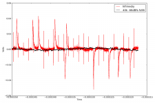
However, looking at the spectrum is misleading, it doesn't tell you about slew rate for example. So, juts looking at the output waveform tells you a lot. Attached is ES9023 output from hifimediy compared to another ES9023 DAC, both playing -66dBfs sinewave.
Attachments
I said the below 1 watt distortion of the Hypex is rather good. You would never guess it from this. I was so perplexed as to use my old scope. With my filter the distortion is as Hypex say. The amplifier sounds rather good considering.

Andrew, are you referring to my trace or Nigel's ?
The small steps on the black trace are the SD modulator output levels from my ES9023. This is normal. A little bit of lowpass, like second order, would get rid of them. But their slew rate isn't that high. Not enough to upset even a slow opamp.
The red trace is hifimediy output. Since they run it at something like 12MHz instead of 50, the modulator has much less cycles to work. It pushes its noise to a lower frequency, where the output filter is less effective. That explains the large pulses that look like RC discharge.
The small narrow spikes are leakage from USB clock, USB chip CPU, spdif, the layout on this is just a failure of epic proportions. Especially the grounding (but not just the grounding). Everything that happens on the board leaks in the output. Since the output filter caps are red wima cubes (and not proper C0G SMTs) they suck at HF. It goes straight through.
ES9023 doesn't spit out that much HF garbage : even without the output filter cap, it's quite clean. To get that red trace, you really have to put all your heart into doing the worst possible layout.
The common mode noise between the USB cable and the analog cable is about a zillion times worse. Which is to be expected, as both cables are at opposite ends of the board, with a CPU in the middle, no plane, and both cables GNDs are linked by a wimpy trace which also carries ground return for the cpu, the DGND, the clock, everything. There is no FCC/CE logo on this, I wonder why... ahem...
- Status
- Not open for further replies.
- Home
- Amplifiers
- Power Supplies
- Broadband Noise