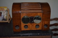
I've just landed this Goblin clock radio for restoration.
Anyone got any idea where to find a schematic for it ?
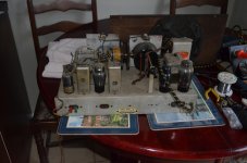
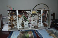
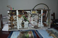
There are three PIO caps which look very wet and a cap that looks as though its been wrapped in bandaid. With no idea what value they should be I'm a bit lost.
Anyone got any idea where to find a schematic for it ?
There are three PIO caps which look very wet and a cap that looks as though its been wrapped in bandaid. With no idea what value they should be I'm a bit lost.
Last edited:
Looks like Radio museum have it but will cost you a membership to get it. Goblin Time Spot Radio S 25 Radio British Vacuum Cleaner, Le
The set uses five valves,
The initial RF valve is unmarked ?
IF is 6K7G and 6Q7GT.
Output is 6V6G.
Rectifier is GZ32.
The initial RF valve is unmarked ?
IF is 6K7G and 6Q7GT.
Output is 6V6G.
Rectifier is GZ32.
Looks like Radio museum have it but will cost you a membership to get it. Goblin Time Spot Radio S 25 Radio British Vacuum Cleaner, Le
That looks like it, and has same valve compliment except for the rectifier.


Google Is Your Friend....
You are in luck, everything you need to know - goblin-time-spot.pdf
Looks like you have highlighted C1, C2 & C10.
Dan.
You are in luck, everything you need to know - goblin-time-spot.pdf
Looks like you have highlighted C1, C2 & C10.
Dan.
The circuit seems a bit odd to me. If you were to use the PU input, how would you isolate the tuner from the signal path ?
I can't see the Mains Earth connection on the cct diagram. Obviously it is required for safety but could that be why the tuner isn't working ?
Too dark and beer time to play with it now. I'll replace the caps and connect the mains earth in the morning.
Too dark and beer time to play with it now. I'll replace the caps and connect the mains earth in the morning.
I've figured out where the Earth core of the mains cable should be connected. It was connected to the shield connection on the mains transformer.
Unfortunately the aerial connectors on the rear panel are shot. I might just make a permanent connection to them rather than trying to substitute modern 4mm connectors.
Unfortunately the aerial connectors on the rear panel are shot. I might just make a permanent connection to them rather than trying to substitute modern 4mm connectors.
Would it do any harm C10 being a higher value. ie 0.1uF.
No it shouldn't cause problems but if you are concerned (and/or have capacitors rated less than 400v), then put two in series. Gives half capacitance, twice the voltage.
Any dry dielectric will be fine here.
I'm still in the dark as to how you can use the PU input. Surely any radio noise will break through.
I'm still in the dark as to how you can use the PU input. Surely any radio noise will break through.
Yes, it will break through. You tune to a quiet spot on the dial to minimise it.
It is designed for a crystal pickup, not a magnetic one. You should be able to connect an MP3 player (running on battery) to the PU input, the levels will be reasonably compatible and the low impedance of the headphone output of the player will effectively short out any noise from the radio section.
- Status
- Not open for further replies.
- Home
- Amplifiers
- Tubes / Valves
- British Vacuum Cleaner £ Eng Co Ltd - Goblin