No screen shot. 🙁
Re your impedance plot, it appears the cab is tuned around 14-15 Hz [~29 Hz much better], so no way the cab tuning will have an under damped 'bump' anywhere in its BW, neither if sealed assuming the published specs are reasonably accurate.
Re your impedance plot, it appears the cab is tuned around 14-15 Hz [~29 Hz much better], so no way the cab tuning will have an under damped 'bump' anywhere in its BW, neither if sealed assuming the published specs are reasonably accurate.
Here is a screen shot of the enclosure simulation. I do realize that theory / simulation does not capture many nuances and that things may need to be tweaked for real drivers, electronics, room etc. With that said, I'm trying to come up with a decent starting point without it becoming a new career.
This project will likely wind up in a basement 2 channel system at my second home - a bit of an old school system driven by a modified Hafler DH220 (Muscial Concepts) from 30 yrs ago. In my dedicated HT room I use Dirac Live and it made a huge difference -might give a minidsp a shot for this build. My two channel system is CJ tubes with Snell mk.5II speakers and a Velodyne servo sub - still love this combo and will be my reference.
Thanks for all the help and guidance!
This time with the enclosure design..
Attachments
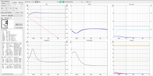
I'm afraid the port tuning is way off, like GM wrote. Besides, with a driver like this Dayton, a port with diameter of 6-7cm is the bare minimum to prevent chuffing. Although with tuning at 15Hz that wouldn't be neccessary, you'd have about no output then 😉
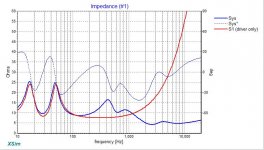
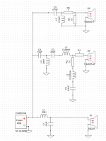
I'm pretty convinced the resonance hump of the woofer impedance is interacting with the 3mF coil for the woofer:
-Try to just bypass the woofer coil, save the FR curve, and then enable the coil again and compare the responses.
-Now, if you see a SPL boost with the coil at LF, try adding a LCR to compensate for the woofer impedance hump and observe what happens.
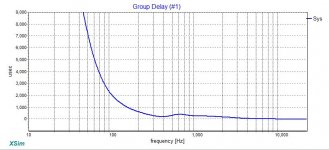
-Also try to look at the group delay when you play around with this. IMHO group delay is important for 'correct/tight' bass.
It gets messy to make a passive XO for a woofer at low frequencies, I guess that's why Troels and many other are going active nowadays. It takes a lot of mH and uF, upside is that for the impedance compensation the wire can be pretty thin in (but I prefer air core), and the caps can be electrolytics.
-Try to just bypass the woofer coil, save the FR curve, and then enable the coil again and compare the responses.
-Now, if you see a SPL boost with the coil at LF, try adding a LCR to compensate for the woofer impedance hump and observe what happens.
-Also try to look at the group delay when you play around with this. IMHO group delay is important for 'correct/tight' bass.
It gets messy to make a passive XO for a woofer at low frequencies, I guess that's why Troels and many other are going active nowadays. It takes a lot of mH and uF, upside is that for the impedance compensation the wire can be pretty thin in (but I prefer air core), and the caps can be electrolytics.
Rallyfinnen
Correct me if I am missing something but if it were a coil/resonance interaction then I would expect to see it on the electrical response graph...which is flat.
Correct me if I am missing something but if it were a coil/resonance interaction then I would expect to see it on the electrical response graph...which is flat.
I don't know, I never looked at the electrical response. Might be some cues in phase if shown? The impedance plot looks odd too, what's the DCR of this woofer?
I think an easy way to test it is as I described. I have done the impedance compensation on a couple of speakers, and always had pleasing first impressions, and even better after tuning it a little bit to the room, using both my ears and microphone.
I am pretty picky with bass though, so it might not be worth it for everybody. I only use sealed boxes (group delay again).

I suggest using Xsim to compare, you can 'hold' a curve in the graph which makes it easy to compare when you make changes. There is also a GD window that can be brought up via the menu.
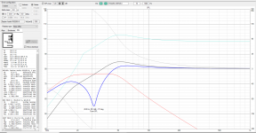
I changed the port to 3"/29 Hz
Need to up it to at least 3.5" and FWIW, HR sims a ~19.29"/49 cm long vent and even then Xmax limited to ~60 W, 14 ms for low GD.
Something is wrong with your Xsim... sim - you shouldn't be seeing 13 ohms impedance at 100Hz with an RS225. Either the impedance data for the RS225 is wrong, or your inductor L1 has an unrealistic DC resistance.
Starting to feel like I'm pushing on a string. Does anyone have a good tutorial on what tools / process should be used and what parameters are the most important to optimize? I started with Xsim based on some post I read. I then used VituixCAD to trace a data sheet plot for the TM4055 to get the frd and zma files since Morel doesn't publish them. I also used VC to get the frd/zma for the RS225 in a ported box. At this stage I hoped I could use proven xo designs for the T&M and Woofer - then tweak things a bit to blend them and flatten the curves. Seemed easy at first but now I seem to be going in circles - if I flatten the curve nicely, I wind up with crazy impedance etc.
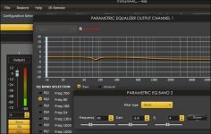
Most important, standing wave at sweet spot.
Slide this one to find it (by ear)
Online Tone Generator - generate pure tones of any frequency
Then set the cut. Click it down a bit, Put on a favorite punchy song, then adjust the gain to be just under what sounds swollen.
(Calibrated standing wave makes all the other bass come forward).
Slide this one to find it (by ear)
Online Tone Generator - generate pure tones of any frequency
Then set the cut. Click it down a bit, Put on a favorite punchy song, then adjust the gain to be just under what sounds swollen.
(Calibrated standing wave makes all the other bass come forward).
Attachments
Last edited:
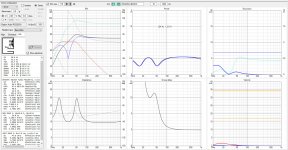
I think I found part of my problem - in VirtuixCAD I was adding in a Rg value which was raising the RS225-8 impedance. PFA the xsim project file and latest plots. Thanks for the help..
Attachments
-
 Fisher-Dayton-Morel-BR-650-lpad-032021-fr.jpg84.7 KB · Views: 83
 -
 Fisher-Dayton-Morel-BR-650-lpad-032021-Z.jpg78.7 KB · Views: 80
 -
 Fisher-Dayton-Morel-BR-650-lpad-032021-GD.jpg63.2 KB · Views: 81
 -
Fisher-Dayton-Morel-BR-650-lpad-032021.dxo92.7 KB · Views: 48
-
 Fisher-Dayton-Morel-BR-650-lpad-032021.png211.2 KB · Views: 92
I got this after 15 mins playing with it, though I haven't looked at phase etc yet. Response is extremely flat with much less driver overlap and a simpler circuit.
Your raw Woofer response (basically a flat simulationabove LF roll off) is not going to be realistic at all as it doesn't account for baffle step effect. You really need a measured response, mounted in the cabinet, to get anything useful there. The same goes for midrange and tweeter.
Your raw Woofer response (basically a flat simulationabove LF roll off) is not going to be realistic at all as it doesn't account for baffle step effect. You really need a measured response, mounted in the cabinet, to get anything useful there. The same goes for midrange and tweeter.
Attachments
Last edited:
@TimA thanks for the design - looks great. I guess I'll have to investigate how to do a measurement of my own.
- Home
- Loudspeakers
- Multi-Way
- bring down the bass hump