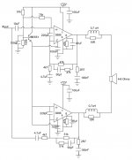
I'd like to run two bridged LM3886 chips from a single-sided 72V power supply. Using the single-sided schematics from the datasheet, I've drawn, but not tested, the attached schematics. Can anyone tell me if I'm going in the right direction? I'm in particular unsure if the circuitry creating the artificial ground/zero voltages should be wired differently for the inverting (lower) amplifier.
Any help appreciated.
Any help appreciated.
Attachments

The non-inverting input on the lower amp need to go to the pseudo-earth not 0V. Shouldn't the 91k/100k potential divider be equal?
If I was going to experiment with this, I'd build 2 identical single-rail circuits exactly as per the datasheet, NOT omitting the DC blocking cap at the output as your circuit does and I'd drive them with a differential driver.
Oh, your schematic could be better drawn, you should not join 4 wires at a point (crossroads) which is old-fashioned, but rather create 2 T-junctions.
Wrong

Right

w
Oh, your schematic could be better drawn, you should not join 4 wires at a point (crossroads) which is old-fashioned, but rather create 2 T-junctions.
Wrong
Right
w
Last edited:
I'd like to run two bridged LM3886 chips from a single-sided 72V power supply.
Again?😡
Regards zeoN_Rider
I'd like to run two bridged LM3886 chips from a single-sided 72V power supply. Using the single-sided schematics from the datasheet, I've drawn, but not tested, the attached schematics. Can anyone tell me if I'm going in the right direction? I'm in particular unsure if the circuitry creating the artificial ground/zero voltages should be wired differently for the inverting (lower) amplifier.
Any help appreciated.
Why? If any speaker line ever touches ground the whole thing goes poof. Why two bias networks? Wouldn't the difference between the two networks show up as offset differences? Or are you planning to SOT? (Select On Test)
I would not do something with built in failure modes.
G²
The non-inverting input on the lower amp need to go to the pseudo-earth not 0V. Shouldn't the 91k/100k potential divider be equal?
Thank you, updated the schematics. The voltage divider is drawn like that in the datasheet, I guess the difference is supposed to compensate for the Vbe voltage of the 2N5551 transistor?
What are you suggesting instead - using output caps?Why? If any speaker line ever touches ground the whole thing goes poof.
Why two bias networks? Wouldn't the difference between the two networks show up as offset differences?
Thought it'd make the chips happy, but I guess one will do as well. Would I need to use a transistor with more current sourcing capability when bridging it?
Again?😡
Regards zeoN_Rider
Just starting my own thread to avoid spamming/hijacking the other one...
Attachments
exactly!If I was going to experiment with this, I'd build 2 identical single-rail circuits exactly as per the datasheet, NOT omitting the DC blocking cap at the output as your circuit does and I'd drive them with a differential driver.
or build two identical inverting amplifiers.
Thank you, updated the schematics. The voltage divider is drawn like that in the datasheet, I guess the difference is supposed to compensate for the Vbe voltage of the 2N5551 transistor?
What are you suggesting instead - using output caps?
Thought it'd make the chips happy, but I guess one will do as well. Would I need to use a transistor with more current sourcing capability when bridging it?
Just starting my own thread to avoid spamming/hijacking the other one...
I never advocate the use of capacitors if they can be avoided. To that end I strongly favor dual balanced power supplies and as much direct coupling as possible. This is somewhat easier in video (my main design area) but also to a large degree in audio as well.
You'd probably get a chuckle out of the High Definition telecine design I was part of. Each channel (R,G,B) has 59 opamps and multipliers with 1 'coupling' capacitor which is in fact an in-line sample and hold capacitor. The 'servos' all use operational transconductance amplifiers (voltage in, current out) as they are drastically better than the opamp integrators I see in the servoed amps here. The integrators dither by necessity as the only way to stay centered is to 'wobble'. It's apparently inaudible but it's certainly visible in a TV picture and it's not pretty. I wonder if the OTAs would be suitable for audio amps.
G²
Scary, scary what you're trying to do here. I may be an idiot, sir, but what I am not, is an idiot- pick up a transformer made for this kind of job. I'm sure someone on this site has one they will sell you cheap cheap.
Unless you make your case out of ABS plastic.
Unless you make your case out of ABS plastic.
please start a new servo thread and tell us more.The 'servos' all use operational transconductance amplifiers (voltage in, current out) as they are drastically better than the opamp integrators I see in the servoed amps here. The integrators dither by necessity as the only way to stay centered is to 'wobble'. It's apparently inaudible but it's certainly visible in a TV picture and it's not pretty. I wonder if the OTAs would be suitable for audio amps.
Scary, scary what you're trying to do here. I may be an idiot, sir, but what I am not, is an idiot- pick up a transformer made for this kind of job. I'm sure someone on this site has one they will sell you cheap cheap.
Unless you make your case out of ABS plastic.
Utter nonsense.
There's absolutely nothing wrong with making a bridged single supply amp and it's no more dangerous than a split supply.
My only complaint with this kind of amp is that essentially it's a waste of an amp channel, which means wasted cost of parts and wasted real estate.
- Status
- Not open for further replies.
- Home
- Amplifiers
- Chip Amps
- Bridged LM3886 from single-sided supply