That's OK Andrew, the stuff that Danielwritesbac is usually non-sense, I've always had trouble understanding his posts.
Mike
Mike
Wooo.... it's finished! and it works no problem at all 🙂
So pleased! My first impressions are it is possibly slightly clearer than my old amp but it isn't very loud and there is very little bass. Still at least it works completely unlike the old one.
Thanks for all your help guys 🙂
So pleased! My first impressions are it is possibly slightly clearer than my old amp but it isn't very loud and there is very little bass. Still at least it works completely unlike the old one.
Thanks for all your help guys 🙂
If you can post a schematic of what you built, we can probably help you with those issues.
Mike
Mike
I don't understand.
The noise you describe and also the "Clear and with very little bass" that the new amplifier does, are related. That noise is impedance mismatch, probably everywhere in the circuit, but with "classic 16 ohm speakers" the worst mismatch is on the output.
Here's the fix to level the response of classic speakers:
(This is not exclusive to classic speakers)

Lenard-Elliot Variable Current Drive
I have won the battle with a Spike chip twice:
Decibel Dungeon Inverting Gainclone (much less noise--a backwards chip amp isn't forward)
Lenard-Elliot Variable Current Drive (for leveling out the non-inverting gainclone)
The previous post was all items that sink the noise (level the response) and the most powerful item on that list is current drive. Variable Current Drive is also called Dial-A-Tube. It is especially applicable because you mentioned output current, and also especially applicable to needs of the speakers on this thread. 🙂
Wooo.... it's finished! and it works no problem at all 🙂
So pleased! My first impressions are it is possibly slightly clearer than my old amp but it isn't very loud and there is very little bass. Still at least it works completely unlike the old one.
Thanks for all your help guys 🙂
Audiosector support forum concerning LM4780 (internally LM3886) suggests a specific model of 1500uF cap at the amplifier board for quality bass. The chipamp.com kit has 100uF and very little bass.
The audiosector support forum also contains other practical examples such as Part CC, the RF and stabilizer cap. Part CC, the RF cap, is also in the LM3886 datasheet from National Semiconductor, the manufacturer of LM3875, LM3886, LM4780 and more. Real datasheets have better clues than kit manuals.
Anyway, those two things, less screech, more bass. Stability and clean power--a good head start.
Maybe bigger caps at the amp are the solution but I'm not sure i'm that worried about it after listening to them for a bit more. The bass might not make the room shake as much as before but I'm getting happier with sound.
I've attached the circuit diagrams anyway. One issue that is cropping up is the blowing of fuses. I've gone through two since I got it working and a few more during testing. Do I just need 3A one instead of 2A? (using a 300VA toroidal transformer). Also, it only goes at start up.
danielwritesbac: My speakers are 6Ohm contrary to the thread title, I didn't have them with me at the time so was going off a photo I found on the net.
Attachments
the close rated fuse for 300VA is either T1A or T1.6A
A robust fuse is ~3times that value to prevent nuisance blowing. But that value of fuse offers little protection.
eg. if you find you need a T4A fuse then it can pass 8Aac in fault conditions for minutes until it finally ruptures. That is 2kW of power to be dissipated waiting for the fuse to blow. Have you looked at a two bar electric fire rated at 1.5kW? Now try to imagine the damage that 2kW dissipating for 3minutes would do inside a small chassis. Would that set the storage cabinet on fire?
You need a soft start to allow a close rated fuse to be used.
Don't believe all those other Members that tell us that one only needs soft starting on toroids greater than 300VA.
Last edited:
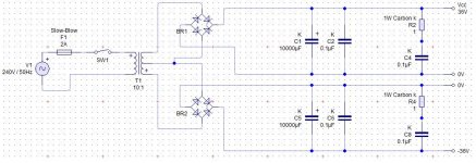
Your power supply isn't wired correctly. If your transformer has two independent secondaries, it should be wired like the top example in the picture below. If it has one secondary with a center tap, it needs to be wired like the lower example.

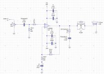
Also, the input and feedback network DC blocking high pass filters are wrong. The input high pass filter has a minimum 1.4 Hz Fc with VR1 set for center position. The feedback network high pass Fc is at 5 Hz. With that configuration, the amp could have input frequencies that the feedback network won't be able to control, input Fc should be at least twice as high as feedback Fc. I recommend replacing the input cap with a 3.3uF for a Fc of about 3 Hz, and the feedback cap with a 220uf for a Fc of about 1 Hz.
And it you should increase C11 and C13 to at least 470 uF, but bigger is better.
Mike
Oh first of all I've drawn the transformer incorrectly, it is as you suggested, those are old diagrams which I just updated today.
I'll consider some bigger capacitors for C11 & C13 if I think I need the extra bass (still not sure). As for the feedback and input capacitors... i really not sure I can be bothered to replace them at the moment. I'm kinda glad to have it finished as it took longer than than I thought (to do the wiring anyway).
I'll consider some bigger capacitors for C11 & C13 if I think I need the extra bass (still not sure). As for the feedback and input capacitors... i really not sure I can be bothered to replace them at the moment. I'm kinda glad to have it finished as it took longer than than I thought (to do the wiring anyway).
OK, but as I've stated before, it is not designed properly, having input Fc set lower than feedback Fc could lead to instability and incresed distortion, this is not a trivial matter.
Mike
Mike
Well, after you correct your power supply. . .
Soft start?
The LM3886 standby feature can be used to soft start, with Pin 8 and the 100uF cap resistor delay thing. Adjust resistor and or cap values for longer delay.
Insufficient bass?
Popular causes of insufficient bass are:
NFB cap is too small, forming a bass blocker.
Input load is insufficient. See the datasheet, page 1.
Preserve speakers?
While testing conditions and fuse blowing is in progress, adopt an output cap to protect speakers. See the datasheet--the cap will be large.
If blocking DC away from the speakers happens to stop the fuse blowing too, please report that.
Test for speaker-amplifier mismatch?
6 ohm speakers. Okay. Output impedance mismatch is less likely but could be present. Test for necessity of adjustment with a much simpler test--just stick approximately a 4 ohm resistor series to the speaker and see if the speaker response is flatter or just sounds nicer. If when that is the case, replace the resistor with a variable current drive circuit. Now, isn't that easy?
Hmm.. ok. I tried a 5Ohm resistor in series with one of the speakers and I don't think it sounded better, even less bass and reduced treble. Although maybe I am hearing a brighter sound from the speaker without the resistor and equating that to 'better' treble performance.
My current mute arrangement is a 10k resistor to -V, and a 100uF capacitor to ground (both starting at pin8) so I suppose it would be easiest to put in a bigger resistor, I have some 22ks.
As for keeping the speakers safe, I don't have any big capacitors to hand but I do have 1 test speaker which I don't mind putting in danger.
To clarify, the negative feedback capacitor is C16 in my diagram, the 47uF one. Would a 100uF make an appreciable difference here or do I need bigger still?
Hmm.. ok. I tried a 5Ohm resistor in series with one of the speakers and I don't think it sounded better, even less bass and reduced treble. Although maybe I am hearing a brighter sound from the speaker without the resistor and equating that to 'better' treble performance.
More bass, less treble and less power is the intended effect of testing with a 4 ohm resistor. Larger values won't make a valid test. Smaller values are still valid for testing. Variable Current Drive gives that same sound effect, without the power loss. This is the means to make a single chip amp sound similar to the AN1192 multi-chip applications. Try slightly less bright, without the overkill.
EDIT: I'm surprised that we're doing the rarest and least necessary quality control first. Please do resolve that fuse blowing problem soon, and please do check for speaker frying DC offset.
Last edited:
My current mute arrangement is a 10k resistor to -V, and a 100uF capacitor to ground (both starting at pin8) so I suppose it would be easiest to put in a bigger resistor, I have some 22ks.
. . .
To clarify, the negative feedback capacitor is C16 in my diagram, the 47uF one. Would a 100uF make an appreciable difference here or do I need bigger still?
Pin 8 of LM3886 requires a certain amount of current from that resistor, to firmly cancel the mute. A too high resistor value can make a weird sound, so, the safe bet is a bigger cap for a greater delay.
A better question would be: Why is there a need to increase the start up delay?--please check over the rest of the circuit for error.
Neither the 47uF nor the 100uF are large enough to avoid forming a bass blocker, but 47uF//100uf, together they are large enough. For more entertaining treble, you can also add a tiny value film cap, like 0.022uF (22nF) or smaller for an extremely small clarity increase.
Ok lol, I'll order some 1500uF caps to go across the supply close to the chip (replacing the 100uF).
I already have 4 spare 100uFs which will be put in parallel with the NFB cap (47uF) and in parallel with the cap in the mute circuit.
This should hopefully solve the bass, the fuse blowing and the potential for low frequency instability 🙂
I already have 4 spare 100uFs which will be put in parallel with the NFB cap (47uF) and in parallel with the cap in the mute circuit.
This should hopefully solve the bass, the fuse blowing and the potential for low frequency instability 🙂
don't expect any of those cap changes to alter the fuse blowing.
This is a quite separate problem.
Have you built and used the bulb tester to power up the transformer and PSU?
Have you thouroughly checked the PSU before attaching the amplifier/s?
This is a quite separate problem.
Have you built and used the bulb tester to power up the transformer and PSU?
Have you thouroughly checked the PSU before attaching the amplifier/s?
Ok lol, I'll order some 1500uF caps to go across the supply close to the chip (replacing the 100uF).
I already have 4 spare 100uFs which will be put in parallel with the NFB cap (47uF) and in parallel with the cap in the mute circuit.
This should hopefully solve the bass, the fuse blowing and the potential for low frequency instability 🙂
No, not really. That doesn't stop fuse blowing. Bigger delay switch on provides only a mild relief. Check further for error. Something should be getting hot with that fuse blowing business, and whatever the hot thing is has a severe error.
P.S.
1500uF//100uF will keep the sound you're used to and add the bass to it. -or-
Replacing 100uF with 1500uF will replace the sound you're used to with a warmer sound.
Surely the problem is caused by the large transient currents at power on. It there were a fault, the amp would not operate at all and the fuse would always blow, or at most operate for a few seconds, I've had it going for hours. I think it is the result of powering on at the crossing of 0V from the mains. If this the case, would a delay in turning on the amp help at all? Is it a soft start circuit that I really need (the biggest current draw being from the transformer and PSU caps)?
Daniel how bad do you think it would be to have quite long leads on the 100uF cap across the supply close to the amp? If I were to add 1500uFs and keep the 100uFs then they would need to lie flat with leads of 5-10mm to reach in under the larger cap. I've read that leads close to the amp should be kept short to minimize any inductance. Would I experience any other problems or would the 100ufs just have less effect at the top end of the frequency range, as their impedance rises (due to parasitic inductance)?
Daniel how bad do you think it would be to have quite long leads on the 100uF cap across the supply close to the amp? If I were to add 1500uFs and keep the 100uFs then they would need to lie flat with leads of 5-10mm to reach in under the larger cap. I've read that leads close to the amp should be kept short to minimize any inductance. Would I experience any other problems or would the 100ufs just have less effect at the top end of the frequency range, as their impedance rises (due to parasitic inductance)?
Last edited:
Surely the problem is caused by the large transient currents at power on. It there were a fault, the amp would not operate at all and the fuse would always blow, or at most operate for a few seconds, I've had it going for hours. I think it is the result of powering on at the crossing of 0V from the mains. If this the case, would a delay in turning on the amp help at all? Is it a soft start circuit that I really need (the biggest current draw being from the transformer and PSU caps)?
Problems like ground loops, instability and DC offset are some possible causes of abnormally high current. When one or more errors occur at the same time as inrush, the combination results in a blown fuse.
Do you have 1 ground wire, from power star ground, to each amplifier board, or do you have ground loop(s)?
Do you have 1 ground wire from power star ground to speaker jacks or is it convoluted?
Did you install the RF filter cap, per the datasheet? That part also promotes stability, according to the datasheet. Stable amplifiers draw less current and run cooler.
Did you put a multimeter to the speaker jack, set to read small amount of DC and confirm that output is less than 100mv DC offset? Zero would be good.
If you checked everything under the sun AND also have a cool running amplifier, then its possible that the fuse values might be optimistic, so you might check on that to see about correct fuses.
P.S.
The circuit illustrated has loudest possible mids--so if you want to hear more bass, either tame down the mids cleanly by design or boost up the bass via added circuitry, such as a baxandall. So, there's two options and there are probably quite a few more available.
Blue Eagle, are you using a fast acting fuse or a thermal delay type? Fast acting type will always be prone to turn-on surge blowing, using a thermal delay fuse of the appropriate current rating will minimize the problem.
Mike
Mike
- Status
- Not open for further replies.
- Home
- Amplifiers
- Chip Amps
- Bridged chipamp for 16Ohm speakers