I wish to make a 200 W subwoofer amplifier using LM3886 in Bridgd and parallel configuration.
I made PCB layout for PA100 configuration. And using a signal splitter (Inverting and Non-inverting ) to run 2 PA100 modules in Bridged form.
The circuits and PCB is as shown. Before Etching i just want to make sure the circuit is OK, just want to get it checked guys..
Thanks.
AUdio Signal SPlitter - http://picasaweb.google.co.in/kuldeep1/BPA200#5287379099025389842
PA100 Circuit - http://picasaweb.google.co.in/kuldeep1/BPA200#5287379095145871522
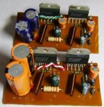
PA100 PCB - http://picasaweb.google.co.in/kuldeep1/BPA200#5287383031831745938
I made PCB layout for PA100 configuration. And using a signal splitter (Inverting and Non-inverting ) to run 2 PA100 modules in Bridged form.
The circuits and PCB is as shown. Before Etching i just want to make sure the circuit is OK, just want to get it checked guys..
Thanks.
AUdio Signal SPlitter - http://picasaweb.google.co.in/kuldeep1/BPA200#5287379099025389842
PA100 Circuit - http://picasaweb.google.co.in/kuldeep1/BPA200#5287379095145871522
PA100 PCB - http://picasaweb.google.co.in/kuldeep1/BPA200#5287383031831745938
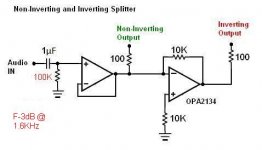
audio splitter circuit.
The output offset from each of the opamps is not near zero.
The resistor values are all wrong to match resistances on the inverting and non-inverting inputs.
Fortunately you have specified a FET input opamp that has inherently low input offset current and this will reduce the output offsets.
For good bass the power amp should have a turnover frequency <=2Hz.
I would recommend that the preamp feeding it should be at least an octave below this, i.e. <=1Hz.
Your 1uF & 47K have F-3dB @ 3.4Hz.
3u3F or 4u7F would be better for a DC blocking cap.
Add RF attenuation to the input.
I see you have DC blocking at the power amp inputs. All you lose due to output offset is available voltage swing before clipping.
PA100 schematic.
Copy the National schematic recommendations and read the whole document to ensure nothing is omitted. Many of the optional features are not really optional and are usually omitted from the simplified diagrams. I don't like the Zobel being moved to after the L//R. I would rather see a separate Zobel for each chipamp. try reducing the 10r in the L//R to 4r or 5r, maybe even lower.
Add in the 0r1 resistors to help balance the outputs from the parallel pair.
Select the resistors to <0.1% matching. Absolute accuracy is not important, matching is very important. Consider adding DC offset servo for each chipamp just as National show.
Add RF attenuation at every input.
After you have added back in all the missing components, consider whether a BPA is worth all the bother and complication when better performance can be obtained with an LME489x0 driver chip and a separate output stage. Or just go fully discrete.
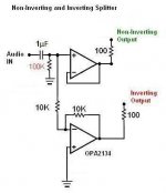
AndrewT said:audio splitter circuit.
The output offset from each of the opamps is not near zero.
The resistor values are all wrong to match resistances on the inverting and non-inverting inputs.
is this Circuit better than previous..
2. I am using matched resistors with .1% (checked using multimeter).
3. The placement of Zobal in this way reduced component count as well as simplifier PCB layout, but functionally it still maintains the stability due to loudspeaker cabaling effect.
Attachments
AndrewT said:this will not work.
Read up on how opamps operate.
ya. thnx.. placed a resistor wrongly
this was the circuit which i initially had in mind. How abt this one.
Attachments
- Status
- Not open for further replies.
- Home
- Amplifiers
- Chip Amps
- Bridged 2XPA100 for Subwoofer, Plans