cm961 said:It looks like a very nice amp, I hope mine turns out like that
As soon as I get a mill machine and start making two sided PCBs, the possibilities will be endless.
Pete
Mills are certainly affordable:
http://www.harborfreight.com/cpi/ctaf/Displayitem.taf?itemnumber=44142
PCB Mills are not that expensive, either.
http://xenonresearch.com/html/xenpcb.shtml
If anyone is interested those nice 1% non inductive metal output damping resistors informational PDF is available here: Vishay/Dale output resistors The ones shown in Kuei Yang Wang's pictures are sold @ Mouser for $1.03 USD Mouser
-Tom
-Tom
I'm wondering. Why doens't it have elec caps (i.e. 1000uf) near each chip? How is power sent to each chip enough?
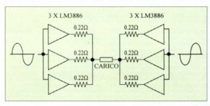
Is six LM3875 / LM3886s per channel better than one? Certainly more power. Less heat stress on the chips, lower output impedance. Would it also have a better S/N? Not sure. Sound better? Dunno.
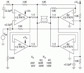
Looks like fun to try though. I found the following app note from Apex to be useful:
Apex Application Note #20
Looking through it, one needs to pay attention to the slave amps since they run in unity gain and thus less stable than the main amp which can have a gain of 20 or 30 or so. They recommend using noise gain compensation.
That's if you are going to configure it all as a parallel bridge. Using an input transformer as a phase splitter and running all the amps directly from the tansformer output signal removes this issue completely. :-/
/R
Attachments
in this case also this threads are of interest.
http://www.diyaudio.com/forums/soli...1-schematic-modules-wanted-5.html#post3782041
http://www.diyaudio.com/forums/chip-amps/131275-jeff-rowland-concentra-amplifier.html
http://www.diyaudio.com/forums/chip-amps/16396-bridgeclone-rowland-concentraclone.html
http://www.diyaudio.com/forums/chip...ons-tda7293-tda7294-lm3886-etc-available.html
Who have saved this images and can upload here ?Koinichiwa,
I just came across some hi-rez internal shots from the new Cncentra. It may be of interest to those seeking to "clown around" with "Bridges over the River Kwai" and the like....
First the overview:
An externally hosted image should be here but it was not working when we last tested it.
As can be seen, unlike the other Rowland Amps that use switch mode supplies, the concentra still does it the oldfashioned way...
The inputs are switched by little, very familiar looking relais, goldflash over copper contact IIRC and then you get a nice Jensen Input Transformer:
An externally hosted image should be here but it was not working when we last tested it.
There is a lot of jiggery pokery and to those who already know, the Concentra uses the CS3310 as volume control.
The following picture shows parts of the PSU, pretty basic, single bridge with ceramic snubber caps, 4 pcs Nichicon PSU Cap's, I'd guess from the looks 10,000uF/63V each:
An externally hosted image should be here but it was not working when we last tested it.
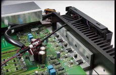
Now onwards to one of the six Nat Semi LM38XX (we know they are 3886) output chips in bridge/parallel:
An externally hosted image should be here but it was not working when we last tested it.
No sign of a servo. Dale 0.2R 1% Output Resistor. All else SMD, including the two local decoupling caps which are by the looks X7R or possibly even Z/Y5U Multilayer Ceramics. All the other SMD resistors appear to be tight tolerance (guess) and there is no manual offset correction either. The paucity of passive components suggests BTW inverting mode....
Sayonara
Who have saved this images and can upload here ?
Hi Found this with lots of pics: JRDG Company Special – Concentra 1 | HFA - The Independent Source for Audio Equipment Reviews/
Cheers
- Status
- Not open for further replies.
- Home
- Amplifiers
- Chip Amps
- Bridgeclone - Rowland Concentraclone