Hi, Ouroboros,
Thanks for the tip 😀. The differential pair is centered at 21V, and the collector legs are sending signal to comparator which sits at 0V?
Hi, EVA,
What is the optimal Vp-p of the residual carrier should be? I have 1V2p-p residual at idle.
Thanks for the tip 😀. The differential pair is centered at 21V, and the collector legs are sending signal to comparator which sits at 0V?
Hi, EVA,
Do you mean small residual is not good?(the more the better noise margin)
What is the optimal Vp-p of the residual carrier should be? I have 1V2p-p residual at idle.
Hi Lumanauw, did you get the block-level schematic I sent to you as a result of your email to me?
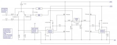
Attached (I hope) is a simple schematic showing how a bridged UCD-style amp can be constructed using only unipolar power rails.
it should be enough to give an idea of one way to do it.
I would suggest that an IRS20124 would be a better gate driver than the LM5106 as although the LM5106 has a settable dead time, the minimum is 80nsec. (This is ok for my low-quality PA application, and gives me around 0.1% THD at 1kHz (measured using ARTA/STEPS), but the dead time really should be lower than this).
Apologies for the poor quality picture, the website requires that the picture is no more than 1000 pixels wide. It should just be readable I hope.
Attachments
Hi, Ouroboros,
Thanks 😀
-There's no half-voltage reference anywhere in the cct, especially not in the differential inputs. Is the output will be sitting automaticly at 24V (when rail is 48V)?
-How to calculate the value distribution of C3(100nF), C4(100nF) and C5(330nF)?
-What is C10(100pf) for?
Thanks 😀
-There's no half-voltage reference anywhere in the cct, especially not in the differential inputs. Is the output will be sitting automaticly at 24V (when rail is 48V)?
-How to calculate the value distribution of C3(100nF), C4(100nF) and C5(330nF)?
-What is C10(100pf) for?
With the dc blocking of the input capacitors, the differential amplifier bases will self-bias at half the output supply rail.
The two transistors in the diff-amp need to be fairly well matched, as an imbalance will affect the output dc offset across the load.
The 100pF capacitor is part of the components to set the gain/phase characteristics of the NFB network (just the same as in any UCD-based amplifier).
The two transistors in the diff-amp need to be fairly well matched, as an imbalance will affect the output dc offset across the load.
The 100pF capacitor is part of the components to set the gain/phase characteristics of the NFB network (just the same as in any UCD-based amplifier).
In the output filter, theoretically you only need the capacitor across the load as part of the filter. If you do that however, you will get a considerable common-mode output RF noise problem. The 100nF capacitors provide a path to 0V for the common-mode signal. Together all three capacitors form the output filter in conjunction with the two inductors.
Hi, Ouroboros,
Is it a problem if we make the one accross the load=220nF, and the 2 that goes to ground also=220nF?
Is it a problem if we make the one accross the load=220nF, and the 2 that goes to ground also=220nF?
- Status
- Not open for further replies.
- Home
- Amplifiers
- Class D
- Bridge with two self-osc ClassD amps?