i am a bit confused, just as i thought i was getting to understand about how these work.
in the picture attached are two diagrams.
figure 1 shows a snap shot of the one in the amp im working on
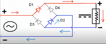
figure 2 shows, what i assume is a typical set up of one of these guys,
what i am confused about is on figure 1 it shows 2 possitive supplies going to the rectifier, where as figure 2 shows it to be +/- to each of the terminals.
am i looking at this incorrectly, or is it the one on my board isnt doing what i think it is?
when the rectifier is on the board there is a dead short between the + and - legs, but not when it is off the board, as i checked it, so there is obviously something a miss elsewhere which i will have to look for, but i just dont understand the diagram.
many thanks
in the picture attached are two diagrams.
figure 1 shows a snap shot of the one in the amp im working on
figure 2 shows, what i assume is a typical set up of one of these guys,
what i am confused about is on figure 1 it shows 2 possitive supplies going to the rectifier, where as figure 2 shows it to be +/- to each of the terminals.
am i looking at this incorrectly, or is it the one on my board isnt doing what i think it is?
when the rectifier is on the board there is a dead short between the + and - legs, but not when it is off the board, as i checked it, so there is obviously something a miss elsewhere which i will have to look for, but i just dont understand the diagram.
many thanks
Attachments
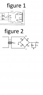
Fig. 2 This is not (+ -), but (~~). This is not a short circuit, but the resistance of the secondary winding of the transformer.
The markings on figure 2 are misleading. The + and - should not be where they are.
Fig 1 is essentially the same configuration but with a centre tap in the mains transformer. This is used to provide a dual or split supply.
Fig 1 is essentially the same configuration but with a centre tap in the mains transformer. This is used to provide a dual or split supply.
i take it that in figure 1 you shouldnt get a direct reading from the fuse holder to ground,as i do.
when i disconnect the lead from the transformer from the board the fuse holder is not then to ground.
when i disconnect the lead from the transformer from the board the fuse holder is not then to ground.
It can be a low resistance 1/2 of the winding of the transformer. The center point of the winding can be connected to ground.
Last edited:
this is a dead short using the audible continuity on the meter
when a transformer is disconnected should you get continuity between the ground and the positive tappings? as if it was a dead short?
when a transformer is disconnected should you get continuity between the ground and the positive tappings? as if it was a dead short?
Check with a multimeter the diodes in the bridge between the terminals in two directions.
a temporary connection to ground during measurement can be obtained through electrolytic capacitors (charge).
a temporary connection to ground during measurement can be obtained through electrolytic capacitors (charge).
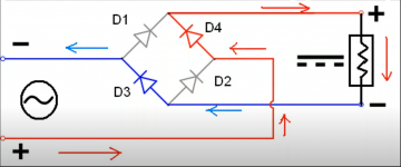
I borrowed these screenshots from youtube... Not my work, but explains how bridge rectifiers works fairly well/ simple. Just imagine Red leaving the source through the rectifiers, through the load, and blue returning to the source(through the rectifiers). They switch direction with the swing.
Cheers,
Tim
Cheers,
Tim
Attachments
It's very simple, tree recifying circuits mixed together.i am a bit confused, just as i thought i was getting to understand about how these work.
, so there is obviously something a miss elsewhere which i will have to look for, but i just dont understand the diagram.
Mona
Attachments

thats great thanks.there are so many items out there that look simlar, its hard to decide whats right,I borrowed these screenshots from youtube... Not my work, but explains how bridge rectifiers works fairly well/ simple. Just imagine Red leaving the source through the rectifiers, through the load, and blue returning to the source(through the rectifiers). They switch direction with the swing.
Cheers,
Tim
cheers, paul
Yes, I found it frustrating at first as well.
Just imagine that both Grounds are connected by a wire (they are electrically connected through a common ground), and the picture I sent shows it in the best way I understand it.
Each rectifier path of a full wave bridge sends out a positive half wave signal, regardless of input polarity . If you only used a half wave bridge, the voltage would have gaps while the source is "reversed", as it wouldn't be able to pass the reverse polarity through the diodes.
All I can think of here is Electroboom with his FULL BRIDGE RECTIFIER!!!
ElectroBOOM - full bridge rectifier compilation (every time Mehdi said full bridge rectifier) - YouTube
ElectroBOOM - full bridge rectifier compilation (every time Mehdi said full bridge rectifier) - YouTube
- Home
- Amplifiers
- Solid State
- bridge rectifier