Hi everyone.
during this time I thought about the way to solve the problems mentioned by Mr. @Elvee.
I can't say with certainty that it was a success but I'll tell you what I did.
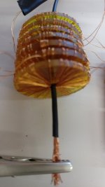
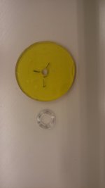
I changed the size and shape (no longer round section but rectangular fig 2) of the toroidal supports which this time are 7.
the dimensions have been changed to increase the area of each single coil and consequently the output signal.
smaller conductor section, this also has importance in its own way.
Below are the details for a single wound toroid:
external diameter 30mm
internal diameter 3.5mm
thickness 2.5mm
number of turns 75
6 micro H inductance
total length of wire 2.45 m
as you can see from the image I used a heat shrinkable sheath to insulate the conductor and reduce the thickness of the insulation.
I made a measurement inspired by the link below:
https://sound-au.com/articles/lock-in-amps.htm
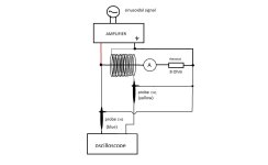
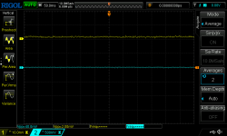
I used the "MEDIA" function of my Rigol oscilloscope then I set the ch2 x1 probe (blue) and the ch1 x10 probe (yellow).
The current flows into an 8 ohm rheostat and then into an ammeter, the diagram is attached.(fig 3)(fig 4).
if the measurements are correct it means that I get around 9mV with a current of 0.5A and 0.9mv at 50mA which more or less corresponds to the minimum volume.
if the 7 toroids become 35 I get 4.5 mV, if they become 70 I get 9mV. This time I haven't checked the resonant frequency but I don't think it is below 2KHz.
I tried to apply the signal on the inverting pin (to increase input impedance) of a µA741 and gain 10.
I didn't need an integrator because I didn't use a frequency range. No output signal.
for this reason I suspect I'm off track again (but I think I'm getting closer to reality) or the µA741 isn't suitable, I have nothing else and I don't have a lock-in amplifier.
to do the litmus test it would be nice if someone tried to do the same thing, or if the voltage of the signal was calculated which for people good at mathematics and physics would be child's play.
I thought of a trick to increase the output signal but this implies an increase in the current which does not pass through the speaker and therefore there is a waste.
furthermore you need to make an additional circuit.
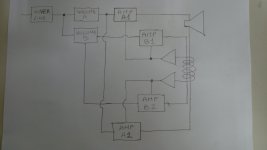
the circuit of volume B works in the opposite way of volume A. when volume A is at minimum volume B is at maximum and vice versa.
in this way the current passing through the coil is always the same, only the current passing through the speaker changes. (fig 1)
during this time I thought about the way to solve the problems mentioned by Mr. @Elvee.
I can't say with certainty that it was a success but I'll tell you what I did.
I changed the size and shape (no longer round section but rectangular fig 2) of the toroidal supports which this time are 7.
the dimensions have been changed to increase the area of each single coil and consequently the output signal.
smaller conductor section, this also has importance in its own way.
Below are the details for a single wound toroid:
external diameter 30mm
internal diameter 3.5mm
thickness 2.5mm
number of turns 75
6 micro H inductance
total length of wire 2.45 m
as you can see from the image I used a heat shrinkable sheath to insulate the conductor and reduce the thickness of the insulation.
I made a measurement inspired by the link below:
https://sound-au.com/articles/lock-in-amps.htm
I used the "MEDIA" function of my Rigol oscilloscope then I set the ch2 x1 probe (blue) and the ch1 x10 probe (yellow).
The current flows into an 8 ohm rheostat and then into an ammeter, the diagram is attached.(fig 3)(fig 4).
if the measurements are correct it means that I get around 9mV with a current of 0.5A and 0.9mv at 50mA which more or less corresponds to the minimum volume.
if the 7 toroids become 35 I get 4.5 mV, if they become 70 I get 9mV. This time I haven't checked the resonant frequency but I don't think it is below 2KHz.
I tried to apply the signal on the inverting pin (to increase input impedance) of a µA741 and gain 10.
I didn't need an integrator because I didn't use a frequency range. No output signal.
for this reason I suspect I'm off track again (but I think I'm getting closer to reality) or the µA741 isn't suitable, I have nothing else and I don't have a lock-in amplifier.
to do the litmus test it would be nice if someone tried to do the same thing, or if the voltage of the signal was calculated which for people good at mathematics and physics would be child's play.
I thought of a trick to increase the output signal but this implies an increase in the current which does not pass through the speaker and therefore there is a waste.
furthermore you need to make an additional circuit.
the circuit of volume B works in the opposite way of volume A. when volume A is at minimum volume B is at maximum and vice versa.
in this way the current passing through the coil is always the same, only the current passing through the speaker changes. (fig 1)
Attachments
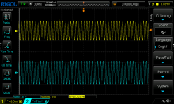
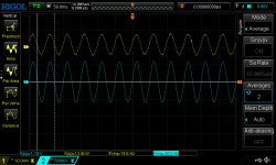
Something strikes me immediately: the amplitudes.
With your test setup, the recovered amplitude should be strictly proportional to the frequency, but here, the amplitude remains almost stable, and it even decreases slightly.
The reactance of the primary of your current transformer is very small compared to 8 ohm driving resistor: its inductance must be in the region of 100nH.
This means that you don't measure what you think you measure: there must be parasitic effects somewhere, maybe with ground connections.
Regarding the shape, your form-factor is not ideal: for a maximum induction, the sensing coil has to envelope the primary wire for as long as possible. Having a large diameter is not advantageous
I must say that the slight decrease in amplitude with frequency surprised me too. Perhaps it is due to the small capacitances present in the probes or the outputs of that old audio amplifier.
what do you mean by transformer primary reactance? are you referring to the conductor carrying 0.5A or to the connected toroidal coils?.
it is true that the intensity of the magnetic field is maximum near the conductor and then decreases as it moves away (Biot-Savart law) but I made the following reasoning, with the total number of toroidal supports being equal if I increase the area of the loop increases the signal however the intensity of the magnetic field inside it is not uniform, if this has a negative influence I don't know, I'm not a physicist.
The primary is the single wire passing inside the coils.
As it is a low value inductance, the voltage across it will be proportional to the current and frequency, and the secondary voltage will be a scaled image of it.
This means that the 60Hz voltage should be 3x the 20Hz one
As it is a low value inductance, the voltage across it will be proportional to the current and frequency, and the secondary voltage will be a scaled image of it.
This means that the 60Hz voltage should be 3x the 20Hz one
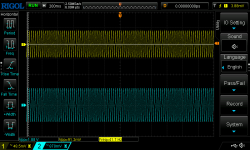
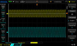
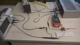
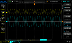
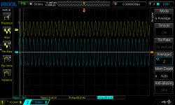
I changed the amplifier and did some other measurements. it is a small amplifier, they are the ones that are usually housed inside the box that contains the woofer. they are the small computer speakers, so to speak. I took out the transformer and PCB. I think the crossover filter is present but I can't be sure. I didn't use the RCA outputs but the output that goes to the woofer. the circuit connections are the same as before.
It was difficult to adjust the volume so as to have 0.5A on all frequencies but I did what I could to achieve it.without adaptation the current changes a lot
the result is in the images.
It was difficult to adjust the volume so as to have 0.5A on all frequencies but I did what I could to achieve it.without adaptation the current changes a lot
the result is in the images.
Attachments
Last edited:
The results are abnormal too: the recovered amplitude is independent from frequency.
I don't see why it is so difficult to keep the current constant: the 8ohm load is fixed and shouldn't depend on frequency, and the generator + amplifier should be equally flat too.
I don't see why it is so difficult to keep the current constant: the 8ohm load is fixed and shouldn't depend on frequency, and the generator + amplifier should be equally flat too.
Note that a current transformer is (mostly) not frequency dependent if it is loaded at the applicable frequencies, i.e. the load resistance is less than the inductive reactance at ~20Hz. That probably requires a ferrite core because the inductive reactance at 20Hz of your air core current transformer will be very small.
With an air core and a single-turn primary, it is a big ask. In fact, Rogowski sensors are almost always inductive, unlike traditional intensity transformers, and they require an integrator in the conditioning process.
I have presented a slightly different version, but it still requires an integrator. The advantage of the (small) core is the improvement of the S/N at VLF
I have presented a slightly different version, but it still requires an integrator. The advantage of the (small) core is the improvement of the S/N at VLF
- Home
- Amplifiers
- Solid State
- bridge amplifier with current sensor