Thanks to Mr. Pass for allowing audio DIYers to use his schematics [in my case F5] so as to communicate ideas like that in this thread.
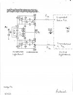
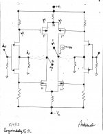
flg, please find attached a pdf and a jpeg of a proposed schematic to bridge a pair of F5s. I hope the following clarifies the subject matter you asked about.
flg, please find attached a pdf and a jpeg of a proposed schematic to bridge a pair of F5s. I hope the following clarifies the subject matter you asked about.
- The Left channel is the familiar schematic of F5 per Mr. Pass.
- The Right channel [not shown] is also the identical schematic of F5 per Mr. Pass.
- The input signals are equal in amplitude, and are 180 degrees out of phase
- Note the resistors which are labelled Rbr [br = bridge].
- The top Rbr connects the source of Q3 of the Left channel to the similar source of Q3' of the Right channel
- The lower Rbr connects the source of Q4 of the Left channel to the similar source of Q4' of the Right channel
- The two Rbr resistors enable the Right and Left amplifiers to freely talk to each other.
- A proposed objective of their open dialog is to lower the net distortion of the resultant differential amp more than due to the parent which does not use the two Rbr bridges [i.e. the baseline]
Attachments
Conjoined Twin diyF5s
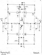
The schematic I showed in Post #1 was unfortunately congested. I simplified it for future analyses in the attached jpg [ConjoineddiyF5s] as follows. The source ports of the P-MOSFETS were directly joined, and the source ports of the N MOSFETS were likewise shorted together. Here is the Introduction Post to my story. Let me tell you up front that I do not own a stereo F5, and do not plan [as yet] to build one or more stereo F5s.
I'll explain..
The schematic I showed in Post #1 was unfortunately congested. I simplified it for future analyses in the attached jpg [ConjoineddiyF5s] as follows. The source ports of the P-MOSFETS were directly joined, and the source ports of the N MOSFETS were likewise shorted together. Here is the Introduction Post to my story. Let me tell you up front that I do not own a stereo F5, and do not plan [as yet] to build one or more stereo F5s.
- Draw a line to join + Vc to - Vc.
- On either side of this line one sees a simplified schematic of diyF5 which is a mirror image of the other.
- I built the Left channel first, connected its +Vin to a low ouput impedance sine wave generator, powered up the amp, and established the recommended stable idle state.
- The function generator was powered but was not enabled to deliver its output signal.
- I put the probes of my scope on the amp's +Out port. To my surprise, the scope showed a 100 mV peak to peak noise signal. I let it be.
- I repeated the above and made the Right channel. Fortunately, this amp was quiet.
- I conjoined the R and L amps per the schematic, connected their inputs to a balanced low output impedance function generator. No signals from the generator were injected.
- Powered up the system. The scope showed a noise signal on the outputs of the Left and Right amps.
- I then connected a loudspeaker from either power output port to ground. I heard a noticeable hiss from either situation.
- I then connected the loudspeaker across the differential power output ports and heard...
I'll explain..
Attachments
Last edited:
Noise will be quite random. The two halves of the balanced stage cannot cancel random noise.
Hum that is the same on both halves but out of phase will cancel.
If the input is actually impedance balanced, then the attenuation on the balanced connection will help reduce common mode interference noise.
Differential mode noise will not be attenuated, unless you implement differential filtering.
Noise will be quite random. The two halves of the balanced stage cannot cancel random noise.
Hum that is the same on both halves but out of phase will cancel.
If the input is actually impedance balanced, then the attenuation on the balanced connection will help reduce common mode interference noise.
Differential mode noise will not be attenuated, unless you implement differential filtering.
AndrewT. As always, thank you for the valuable input. It is specific, and detailed. I admit that I needed the Left amp to be a free wheeling function generator. I chose noise as its output. But, it is best now that I endow the Left amp with the ability to motorboat instead.
Best regards
The make-believe hiss in post#2 was replaced with a low frequency oscillation which was intrinsic to the stand-alone left channel only. The following [Chapter 1] explains the operation of this bridge amp:
analyze the same bridge amp; with both L and R channels not motorboating and processing input signals.
Homework. Use the above procedure to analyze your favorite bridge amp.
- Track one cycle of the signal with its number.
- Start at the +Vout of the Left amp [1].
- Its sole outlet is to ground. and thus reaches the joint source ports of the input JFETs [2]. Signals [1 and 2] are in phase.
- The input JFETs operate in the common gate configuration. Their joint gates is at AC ground.
- Signal [2] moves to the respective drains of input JFETs. I only show a signal at the drain of the N-channel JFET [3]. The ongoing discussion applies fully to identical signals moving through the P-channel JFET [not shown].
- The signals [2 and 3] are in phase; a characteristic of a common gate transistor operation.
- Signal 3 is presented to the gate of the P-MOSFET. This transistor operates in common source mode. It amplifies it and inverts its phase to generate signal [5].
- The superposition of two out of phase signals with unequal amplitudes [5 and 1] still gives +Vout signal 1 of shown positive phase; or incomplete cancelation. It also means that the Left channel continued to motorboat; or its loop feedback did not fully reduce +Vout signal 1 to zero amplitude.
- P-MOSFET also acts as buffer to signal 3. It replicates signal 3 in magnitude and preserves its positive phase to generate signal 4 at the source port of this MOSFET.
- Signal 4 is simultaneously presented to the source of P'-MOSFET.
- P'-MOSFET operates in a common gate configuration.
- Signal 4 generates -Vout signal 6.
- Note that the +Vout and -Vout signals 1 and 6 are in phase. Or the Right amp duplicated the phase and most probably the amplitude of the Left amp's signal 1.
- Moving on, signal 6 becomes 7. Signal 7 enables the in-phase signal 8 at the drain of the N-channel JFET or the gate of the P'-MOSFET.
- P'-MOSFET buffers signal 8 to create signal 9 which is equal to signal 4 in amplitude and of identical phase; since both sources ports are conjoined.
- P'-MOSFET also operates in a common source mode. It amplifies and inverts the phase of signal 8 to generate signal 10.
- The superposition of two out of phase signals with unequal amplitudes [10 and 6] still gives a Vout signal 6 of shown positive phase; or incomplete cancelation.
- Connect a louspeaker at either power output to ground and hear a motorboat.
- Connect the loudspeaker between the power out port of both amps. The oscillation disappears. The [annoying] power out signals did not pass through the loudspeaker.
analyze the same bridge amp; with both L and R channels not motorboating and processing input signals.
Homework. Use the above procedure to analyze your favorite bridge amp.
Attachments
The meat of the matter
The key learning or find in the previous post is. The Right amp generated an exact replica [at its power out] of the original signal at the power out of the Left amp. These two signals are in-phase and of equal amplitude. They did not pass through a loudspeaker connecting said ports.
The conditions for the experiment of this post are:
- Conjoin [pristine] Twin F5s which are are not plagued by problems like motorboating etc.
- Their inputs are connected to a balanced function generator set at 1 KHz.
- The input signal to the Left amp was enabled and the input signal to the Right amp was disabled. The input port of the Right amp is at AC ground.
- Signal #0 of the Fundamental Frequency [1KHz] is amplified in the Left channel and appears at its power out as signal 1.
- Signal # 0 simultaneously stimulated the Left amp to generate at its power output a second harmonic. Signal 1h is this new frequency.
- This harmonic signal 1h has amplitude and phase. It is physically separated [or seperable] from the fundamental signal 1.
- Thus I am able to track the path of each signal [1 and 1h]independently starting from the power out port of the Left amp to their final destination at the power out port of the Right amp.
- Fundamental frequency signals #0 through 5 circulate in the Left amp.
- Fundamental frequency signals 6 through 10 circulate in the Right amp.
- The power out Fundamental frequency signals are out of phase. They pass through the loudspeaker.
- Track the fate of harmonic signals 1h through 10h as shown above for the fundamental .
- The harmonic signals at either power out port are in phase and most likely of equal amplitude. This harmonic distortion does not pass through the loudspeaker. Why? The earlier case of motorboating in the left chanel and the stimulated generation of the harmonic in it are conceptually and thus practically the same phenomenon. Both are absent in the input signal, intrinsic to the Left amp, and spontaneously appear at its output port.
- Gotta go.
Attachments

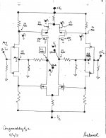
Hear are clear schematics of those shown in above post. I also include a Blank schematic which is unmarked with signal squiggles. Print several paper copies of the Blank and use it to practice the signal tracking techniques I described above. You are already and/or will be expert in no time.
Best regards
Best regards
Attachments
Operation with common mode signals
This is experiment # 3 out of 4. The + and - Inputs of the conjoined twin F5s [above schematics] are offered a 1 KHz sine signal [Fundamental] of equal amplitude and of identical phase. Here is the favorable outcome
This is experiment # 3 out of 4. The + and - Inputs of the conjoined twin F5s [above schematics] are offered a 1 KHz sine signal [Fundamental] of equal amplitude and of identical phase. Here is the favorable outcome
- The amplified power output Fundamental signals are equal in amplitude and have identical phase; provided the Left and Right amps have similar closed loop gain.
- Connect a loudspeaker between the two power output ports. No Fundamental signal current flows through it.
- This is an expression of rejecting a common mode input signal.
- The input signals stimulated each amp to generate its own blend of harmonics.
- The loudspeaker is still silent; what's going on? I hope that you are not surprised.
- Let's play this general game which uses the learnings from the previous posts.
- The Left amp generates a 2 KHz harmonic of amplitude equal L, and a positive phase. By contrast, the Right amp generates a 3 KHz harmonic of amplitude equal R, and a negative phase relative to the second harmonic.
- This distortion [or enriching harmonics] present at the power out ports of the amps do not pass through the loudspeaker connected across them. Here is why.
- The R amp makes a copy of the 2 KHz at its output port. It is exact in amplitude and phase as that originally created by the Left amp. The loudspeaker does not pass this 2 KHz signal [inaudible].
- Simultaneously, the Left amp generates at its power output port an exact replical [in amplitude and phase] of the 3 KHz harmonic initially synthesized at the power out port of the R amp. The loudspeaker does not pass this 3 KHz signal.
- The Conjoined Twin F5s processed the harmonics like the common mode Fundamental 1 KHz at its inputs.
DIDO operation of Conjoined Twin F5s
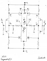
In this experiment, the + and - inputs of this amp are offered 1KHz signals [Fundamental] of equal amplitude, and 180 degrees out phase with each other. A schematic is attached. Follow the signals 0 through 4 for the Left amp, and signals 0' through 4' are for the Right amp. Here is the favorable outcome:
In this experiment, the + and - inputs of this amp are offered 1KHz signals [Fundamental] of equal amplitude, and 180 degrees out phase with each other. A schematic is attached. Follow the signals 0 through 4 for the Left amp, and signals 0' through 4' are for the Right amp. Here is the favorable outcome:
- The amplified 1 KHz power output signals pass through the loudspeaker as expected.
- Note the absence of signal [Null] at the joint source ports of the P-MOSFETs, and N-MOSFETs [not shown].
- Note the intrinsic harmonics of the Left [4h] and Right [4h'] amps.
- Harmonic 4h from the Left amp crosses the bridge at the joined source ports of the P-MOSFETs and is dupliucated in amplitude and phase at the power output of the Right amp. Harmonic 4h does not pass through the loudspeaker.
- Simultaneously, harmonic 4'h from the Right amp crosses the bridge at the joined source ports of the P-MOSFETs and is duplicated in amplitude and phase at the power output of the Left amp. It does not pass through the loudspeaker either.
- Prevents or rejects the flow of common mode signals which are input to the L and R amps.
- Equally prevents or rejects the flow of distortion signals which are internally generated by the L and R amps.
- Passes the fundamental and differential power output signals.
Attachments
Two issues remain
Issue #1: What if I operated the R and Left amps without loop feedback in the conjoined twin F5s? Consult the attached.
Best regards.
Issue #1: What if I operated the R and Left amps without loop feedback in the conjoined twin F5s? Consult the attached.
- Admit a Fundamental 1 KHz Signal# 0 to the Left amp. Ground the input to the Right amp. This is single-ended input [SEI] operation.
- Signal 4 is amplified Signal 0 and is in-phase with it.
- P-MOSFET [Left ch] buffers Signal 2 to generate Signal 3 on the bridge of the joined source ports of the P MOSFETs.
- Signal 3 is amplified by P'MOSFET [Right ch] operating in common gate configuration to create Signal 5.
- Signals 4 and 5 are out of phase with each other at the power ouput ports of the amp.
- Connect a loudspeaker between these two output ports. It sings as expected.
- The conjoined twin F5s is a SEIDO or single ended input to differential power output.
- Make believe that P-MOSFET [Left ch] is notorious for generating the harmonic.
- Make believe the other 3 power output devices are void of the ability to generate harmonics.
- Here is the crux of the issue. What is the phase of the harmonic at the power output of the Left amp relative to that on the bridge?
- They are shown in phase in the attached for the game. The Right amp makes an exact copy of this harmonic at its power output port. This harmonic does not pass through the loudspeaker because they are in phase and most probably of equal amplitude..
- But; what if the harmonic at the drain and source of the P MOSFET [Left Ch] are out of phase. In this instance an inverted harmonic is generated at the power output of the Right amp. The loudspeaker sings this harmonic; not bad if one loves harmonics.
- The bridges are closed for the Fundamental and are still open to the harmonic.
- The Fundamental and its harmonic are independent signals; separable or they are not chained to each other; unlike crossover distortion which is part and parcel of the Fundamental power output signal.
- It is then possible that the harmonics [of lower amplitude than fundamental] pry open the bridges [do not cut-off the transistors] and thus pass through from one amp to the other for inter-duplication. An improved Class AB operation is expected across the loudspeaker.
Best regards.
Attachments
- Status
- Not open for further replies.
- Home
- Amplifiers
- Pass Labs
- Bridge a pair of F5s