I'm about to build a ZenV4 and want a preamp to go with it.
Since it will be an integrated amp I will have a supply voltage
of approximatley 50V (like the Zen) at my disposal. After having
read Mr. Pass articles on cascoding and DIY OP amps I was
tempted to add som circuitry to the BoZ in order to, hopefully,
improve its performace. So my question to all of you is: Is the
following a good ide? I suppose not since I haven't seen
any attempts to modify the BoZ in a similar matter... But why is
that?
/Niclas
Attachments
Hi,
If this is the case my simulator is _way_ off...
Could you please explain your reasoning?
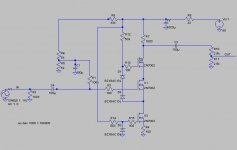
Below is the simulation from LTSpice/SwitcherCADIII with the
above circuit:
This circuit does not work. It has no gain. Output voltage is always 0V
If this is the case my simulator is _way_ off...
Could you please explain your reasoning?
Below is the simulation from LTSpice/SwitcherCADIII with the
above circuit:
Attachments
"I haven't seen any attempts to modify the BoZ in a similar matter"
Yes, that's strange. Cascode is considered as a good thing (unlike NFB that some people like and others dislike)
I was also expecting to see more cascoding modifications, on pass amps. Especially since Mr Pass himself wrote an article about cascoding.
Is there any disadvantage to cascoding (except the lower woltage swing) that could dissuade diyers to try this?
Do not believe everything a simulator tells you. If Q3 works as current source with an (nearly) infinite output impedance it's
obvious that there isn't any voltage deviation on R7 and in this way any voltage gain.
If Q3 saturates I can't see any reason why implementing this MOSFET.
In other words: This circuit works not as expected.
obvious that there isn't any voltage deviation on R7 and in this way any voltage gain.
If Q3 saturates I can't see any reason why implementing this MOSFET.
In other words: This circuit works not as expected.
As bocka says, the gain should be near 0, as the gain will
be the ratio of the output impedance load divided by the
Source resistance of Q1, which with a constant current source
will be very high.
Drop the current source, Ground the Source of Q1 and enjoy
the cascoding provided by Q2.
be the ratio of the output impedance load divided by the
Source resistance of Q1, which with a constant current source
will be very high.
Drop the current source, Ground the Source of Q1 and enjoy
the cascoding provided by Q2.
Nelson Pass said:As bocka says, the gain should be near 0
Sometimes the silence would be very appreciated 😉 .
Thank you bocka and Mr.Pass for pointing out the error.
I didn't think the MOSFET Q3, which can't supply a whole lot of gain, would work that well as a CCS. The purpose was just to try to better the 100 Ohms to ground in the original BoZ.
Now I find I've lost all my faith in Spice simulations!
I didn't think the MOSFET Q3, which can't supply a whole lot of gain, would work that well as a CCS. The purpose was just to try to better the 100 Ohms to ground in the original BoZ.
Now I find I've lost all my faith in Spice simulations!
Spice is just a tool, a fine one at that, but like any tool can
be well or ill used. It is not a substitute for understanding.
be well or ill used. It is not a substitute for understanding.
Spice is just a tool, a fine one at that, but like any tool can be well or ill used. It is not a substitute for understanding.
How very true. 😱
It was som ten years since I read my last electronics course so I have som catching up to do...
May I ask whether you have constructed the BoZ with a cascode and if so how it compares to the original?
/Niclas
Works great. There will be some cascoding going on toward
the end of the Zen Variations series, early next year.
the end of the Zen Variations series, early next year.
Stäppvargen (praire wolf), I think you must think of a couple of things:
1 How much current (how much gm will I get?) do I want in the stage?
2 How much gain do I want?
3 How much gain can I get?
4 How much local feedback do I need?
5 Which value must the source resistor have?
6 How do I create a stable working point? Must I use a servo? Must I use trimpots? Must I use some temperature sensing?
PS: Why don't you add your country flag? Not everyone knows where Göteborg is located.
Nelson,
do you prefer the cascoded stage over the non-casocoded? And how would you discribe the audible differences between them?
do you prefer the cascoded stage over the non-casocoded? And how would you discribe the audible differences between them?
Nelson Pass wrote:
Ah! Just what I wanted to hear! 🙂
peranders wrote:
Hi peranders! Since I will build a ZenV4 which according to my simulations 🙂devilr: ) will distort att input voltages exceeding ~5V (gain is approx. X 4 and usable rail voltage seen by the mosfet is ~42). My thoughts were that the BoZ can use the same single rail (approx. 55V before regulation) as the ZenV4 and probably be a good match for it. One of the good things about using a tried design is that I won't have to thing about everything!!! This being my first amp project and all. Do you disagree?
PS: I'm showing my colors!
Works great. There will be some cascoding going on toward
the end of the Zen Variations series, early next year.
Ah! Just what I wanted to hear! 🙂
peranders wrote:
Stäppvargen (praire wolf), I think you must think of a couple of things:
1 How much current (how much gm will I get?) do I want in the stage?
2 How much gain do I want?
3 How much gain can I get?
4 How much local feedback do I need?
5 Which value must the source resistor have?
6 How do I create a stable working point? Must I use a servo? Must I use trimpots? Must I use some temperature sensing?
PS: Why don't you add your country flag? Not everyone knows where Göteborg is located.
Hi peranders! Since I will build a ZenV4 which according to my simulations 🙂devilr: ) will distort att input voltages exceeding ~5V (gain is approx. X 4 and usable rail voltage seen by the mosfet is ~42). My thoughts were that the BoZ can use the same single rail (approx. 55V before regulation) as the ZenV4 and probably be a good match for it. One of the good things about using a tried design is that I won't have to thing about everything!!! This being my first amp project and all. Do you disagree?
PS: I'm showing my colors!
bocka said:do you prefer the cascoded stage over the non-casocoded? And how would you discribe the audible differences between them?
There is a reason they call this DIY. 😎
Mr. Pass,
Would a hundred ohms in series with the source and current source and a large cap across the current source work?
Regards,
Jam
Would a hundred ohms in series with the source and current source and a large cap across the current source work?
Regards,
Jam
Yes, but why bother with the current source then?jam said:Would a hundred ohms in series with the source and current source and a large cap across the current source work?
Correction: it will work fine with just the resistor. The scheme
you propose will probably work even better in terms of
dynamic range on the input, but is more complex than I think
it would be worth.
Niclas, I suppose you don't want us to design this amp for you but you should take a closer look at the working point of the amp. How do you make a currentwise stable amp? Think also: Avoid trimpots. Use them when nothing else solves the problem.
peranders wrote:
No, seriously, it was the first small signal MOSFET I found in LTspice/SwitchercadIII. It was my first attempt to simulate a electronics circuit so I was just happy to find something potentially usefull.
peranders wrote:
Obviously because of it's superior audio capabilities! 😉why have you chosen the 2N7002, which is in SOT23 package?
No, seriously, it was the first small signal MOSFET I found in LTspice/SwitchercadIII. It was my first attempt to simulate a electronics circuit so I was just happy to find something potentially usefull.
peranders wrote:
I assure you that some help would be appreciated! I'm familiar with my Kirchoffs and Thevinins, but unlinear IV devices like MOSFETs give me the creeps. For instance, what value of Vgs would I likely get when several Vgs seem possible when examining the load line? My rather limited understaning of the circuit is as follows:I suppose you don't want us to design this amp for you but you should take a closer look at the working point of the amp.
Attachments
- Status
- Not open for further replies.
- Home
- Amplifiers
- Pass Labs
- Bride of Zen with cascode and current source.