You should at least have a fuse at the primary side.revell said:one more
how many fuses should one include in a gainclone??
peranders said:You should at least have a fuse at the primary side.
That much is for sure. And if you really want to feel safe, a fast blow fuse on each supply rail.
revell said:I have a problem with my brianGT kit: the chip produced flames and started smoking as soon as I connected the power.
A good argument for a variac with a current meter on first power up.
Another trick is to put a mains voltage low wattage incandescent light in series with the transformer primary. Should nicely limit the current for electrical disasters like the above.
A problem with fuses is that they tend to die after the active electronics.
IMHO, YMMV, yada-yada.
digi01 said:this simple circuit can avoid the mess current when power on the amp.any suggestions?
sch pic below,AC power soft start.
Digi01, thanks for posting a simplified drawing of a a/c power soft start. I sure would appreciate knowing the component values and/or part#'s.
Phil
Q1 Based on relay parameters, would that be the coil rating voltage dcdigi01 said:thank you for your interest.
the values of R1,R2,C1 is mainly based on the relay parameter.
the others component values:
B1- 1N4007 *4
C2 - 470uf/250V safety value
R3 - *20W30(current limit)
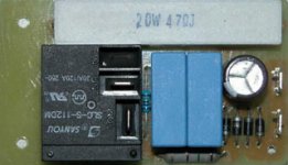
here is the real stuff.
Q2 AC-in, what voltage, 120vac (transformer primary), 18-25vac (transformer secondary), 4-18vac (another transformer used for this circuit)
Q3 Could you show me how to calculate R1, R2, C1 using an example of recommended AC-in?
Thanks Phil
Hi Phil,
>>Q1 Based on relay parameters, would that be the coil rating voltage dc
there are two parameters.one is NOMINAL INPUT VOLTAGE,the other is NOMINAL RESISTANCE.
>>Q2 AC-in, what voltage, 120vac (transformer primary), 18-25vac (transformer secondary), 4-18vac (another transformer used for this circuit)
the soft start circuit should be set up before the transformer primary.
>>Q3 Could you show me how to calculate R1, R2, C1 using an example of recommended AC-in?
Ok,the soft function is achieved by C1 charging.
when you power on the circuit,C1 is in open,during the charging of C1,the voltage of the coil is raising...then it is full worked.
SO,R1>>R2.
R3,10-30 ohm,20W
Some calucations can be pretty hard but you can use my simulation files and put in simplifed values. Consider the relay to be a resistance, for instance.
I have used the free program LTSpice from www.linear.com
Notice that digi's circuit won't do in 230 VAC countries, unless he changes a little. A plain 0.6 W metall film resistor isn't safe in 230 VAC environment.
I have used the free program LTSpice from www.linear.com
Notice that digi's circuit won't do in 230 VAC countries, unless he changes a little. A plain 0.6 W metall film resistor isn't safe in 230 VAC environment.
Attachments
Digi01
Sorry, I don't understand this. I have 120vac before transformer primary. I have 24vdc spdt & dpdt relays, don't know resistance since I'm at work.
Q1 How do I get from the 120vac to 24vdc in your circuit?
Q2 Could you tell me the values for R1, R2, C1
Peranders
I like what you did in your soft start circuit. K2 contacts delayed allows slow feed bypass to transformer.
Q1 How do you get from 120vac to 24vdc in your circuit.
Phil
If you already have 24 volts DC, just skip everything from the rectifier bridge and backwardsmrlots2do said:Peranders
I like what you did in your soft start circuit. K2 contacts delayed allows slow feed bypass to transformer.
Q1 How do you get from 120vac to 24vdc in your circuit.
If you have 120 VAC (instead of 230 VAC), then you have to increase C1 and C2 in my design. I have written at the end of the page suitable values.
a bit OT but i would rather post this in an active thread than start a new one.
If you use the GC based on LM3875 with 2x24V psu unrectified, how much gain can you have on the preamp without driving the GC into clipping? Havin the bottlehead foreplay (19db gain) in mind.
I have i dim memory about reading something about it being a problem when using a CD as source.
If you use the GC based on LM3875 with 2x24V psu unrectified, how much gain can you have on the preamp without driving the GC into clipping? Havin the bottlehead foreplay (19db gain) in mind.
I have i dim memory about reading something about it being a problem when using a CD as source.
peranders said:
If you already have 24 volts DC, just skip everything from the rectifier bridge and backwards
If you have 120 VAC (instead of 230 VAC), then you have to increase C1 and C2 in my design. I have written at the end of the page suitable values.
Peranders, your website and write-ups are amazing. I've read the soft start pages several times now and find something additionally noteworthy each time read. Thanks.
BTW.... I have not yet purchased internationally and was not aware of money exchange charges. The charges listed on your webpages seem a bit high.
Phil
Sigh.
I blew up my first LM4870 board last night; I'd just
gotten it together and was doing initial load testing.
There was a 1 volt offset on the output, and then
it just blew. No obvious distortion, but I had it running
at full power into a 4 ohm load.
You guessed it; no fuses!
It was a pain to get the chip out of the board, but I
didn't lift any traces or pull out any feedthroughs--looks
like a good quality board. The silicon is a pretty good
sized die--it completely separated from its heat sink.
The heatsink wasn't flat and I may have stressed the
package; will remount differently next time. I won't swear
100% that I had the right parts value in the right places.
Where's Brian these days? He hasn't answered email
and hardly seems to be online any more.
I've got a bunch of mica insulators that I cut down to fit;
holes are spaced correctly but it was intended for two
devices side by side. Holler if you need some and I can
put them in an envelope and mail them. I cut them down
for TO-247 packages, too.
--Damon
Because everyone wanted to see some fotos (it is not from a Brian GT board): I like to smoke, but not the smoke from Ampères 🙄
I really dont know, why this happened! Immediately after power on. The amp and the chip "burned in" before about 3 hours.
After replacing the chip: everything is O.K.
Franz
An externally hosted image should be here but it was not working when we last tested it.
I really dont know, why this happened! Immediately after power on. The amp and the chip "burned in" before about 3 hours.
After replacing the chip: everything is O.K.
Franz

- Status
- Not open for further replies.
- Home
- Amplifiers
- Chip Amps
- BrianGT amp burst into flames