I say "custom" because it's based on PSU boards from audiosector and LM4780 bridged boards from tech-diy. I'm using a single Plitron 300VA 18V+18V transformer (keeping the voltage low so I don't need a fan). According to the overture design guide, this voltage gives me approximately 115W per channel. At this point I've decided on a single rectifier board for both amps ("stereo" design). The PSU is going in a separate enclosure from the amp.
On the amp board, I changed some cap types from the example parts list. I changed the 1000uF cap to an FC and the 10uF to an EB. This gives all electrolytics in my system a lifetime of 3000+ hours @105C. All values were kept the same.
The PSU on the other hand, I've changed the design a bit. For smoothing caps, I've selected a 2,200uF FC cap for each rail. I also purchased a pair of 15,000uF TS-HA caps to add if I feel there isn't enough bass. Also note there are 1000uF, 10uF and 0.1uF caps on power on the amp board.
Now, I just read that it's better to put the "storage" caps (15,000uF) in the amp enclosure than the PSU enclosure. Would that be true in this case?
I understand, they're to give quick power when the bass hits, etc. and that the umbilical will reduce the speed with which that power could get to the amp. Also, would I use them in place of the 1000uF caps, or in addition?
My personal preference is to keep the big capacitors far from the amplifier board, after all, bass does not requiere that speed, if it did, then it wouldn't be bass!
The reason, the big pulses that load them will radiate some EFI that you don't want to have near the amp board.
The reason, the big pulses that load them will radiate some EFI that you don't want to have near the amp board.
Thanks for the input! I was hoping to put them in the PSU box, but unsure. First I'm going to test without them though, then jumper them in before I decide to use them or not. I suppose I could compare, jumpered in the PSU box or in the amp box.
I keep my "big" caps 10,000uf on the psu.
if you want to try different caps value,use alligator clips.using alligator clips will make your job easy and fast to compare caps values.(be careful with big caps...They can store a big punch).
SAFETY FIRST!
if you want to try different caps value,use alligator clips.using alligator clips will make your job easy and fast to compare caps values.(be careful with big caps...They can store a big punch).
SAFETY FIRST!
Redshift187 said:
Now, I just read that it's better to put the "storage" caps (15,000uF) in the amp enclosure than the PSU enclosure. Would that be true in this case?
I understand, they're to give quick power when the bass hits, etc. and that the umbilical will reduce the speed with which that power could get to the amp. Also, would I use them in place of the 1000uF caps, or in addition?
I once posted about power supply caps, in one topic long ago.
I told people to put one BIG cap (4700/10000 uf) close to rectifier
and put some smaller 1000 uF close to power output transistors.
I got the following reply from The One and Only Nelson Pass:
it is better to put the other way:
Some 1000 uF right close to rectifier,
and at the Amplifier PCB board put some bigger (4700/10000 uF)
where the V+ and V- connections wires attach to the PCB.
So, as i have never forgot what The Master Nelson told me,
I advice:
1. Put some 1000 to 4700 uF right close to Rectifier diodes/bridge, in PSU unit.
2. Then draw you wires over to Amplifier Case/PCB
3. To the Amplifier Board, where you put in MAIN CAPS: 4700 to 15000 uF
somewhere at PCB V+ and V- intakes terminals.
(4. If you wish, especially if Chip is not very close to MAINS CAPS,
you can also put two 1000 uF right close to the CHIP V+ and V- supply PINS.)
Well,some good designer like to put "big" caps right after brige rectifier. take a look here for a Bryston amp!.http://www.bryston.ca/BrystonSite05/BrystonDocs.html
So at this point I'm almost done populating the PCBs. I bought 2 PSU boards, but only plan on using 1, so I made different PSU configurations that I can swap out to compare. On one, I used only a single 2,200 uF Panasonic FC on each rail.
On the other I used a snubberized setup consisting of the 15,000 uF Panasonic TS with a 0.1 uF Kemet Golden Max ceramic across the pins and a 0.1 uF Vishay MKP plus 1R metal film resistor after that.
I left the 1,000 uF FC caps off the amp boards for now, so I can test without them first, then add them if I want. There are 0.1 uF ceramic and 10 uF electrolytic on the amp board for PSU decoupling (is that the correct term?).
tell us about the results when you have them up and playing.Redshift187 said:So at this point I'm almost done populating the PCBs. I bought 2 PSU boards, but only plan on using 1, so I made different PSU configurations that I can swap out to compare. On one, I used only a single 2,200 uF Panasonic FC on each rail.
On the other I used a snubberized setup consisting of the 15,000 uF Panasonic TS with a 0.1 uF Kemet Golden Max ceramic across the pins and a 0.1 uF Vishay MKP plus 1R metal film resistor after that.
I left the 1,000 uF FC caps off the amp boards for now, so I can test without them first, then add them if I want. There are 0.1 uF ceramic and 10 uF electrolytic on the amp board for PSU decoupling (is that the correct term?).
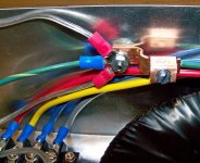
Here is the power star ground. The green/yellow wire heading off on the right goes to the earth pin on the power entry module. The green wire on the left goes to the power exit module. The silver coloured wires go to the ground points on the rectifier board. You can see the terminal block for the transformer secondaries in the bottom left corner.
Attachments
I decided to put the 1000 uF caps on one channel, that way I can do a direct comparison. Got the amp set up and tested DC offset. Looks like about 3 mV on the channel with the 1000 uF caps and 4 mV on the other. Tomorrow I will test with my test speaker, then if all goes well I'll start the burn in.
After burning in the small cap rectifier board and listening to it, I replaced with the large snubberized cap rectifier board, burned it in and listened to it as well. My test speakers are 150W Pioneer 3 way floor speakers. Keep in mind I've only ever owned a Pioneer combo receiver/tuner/eq/cassette setup. My source was a Pioneer DV 353 dvd player, and the material was David Gilmour Live In Concert and David Gilmour Live At The Royal Albert Hall.
Different setups:
1. 2,200 uF per rail on rectifier board and 10.1 uF per rail on amp board. Great mid and high range clarity (3 out of 4). Almost no bass below 150 Hz (1 out of 4).
2. 2,200 uF per rail on rectifier board and 1010.1 uF per rail on amp board. Best mid and high range clarity (4 out of 4). Very little bass below 100 Hz (2 out of 4).
3. 15,000 uF per rail snubberized on rectifier board and 10.1 uF per rail on amp board. Decent mid and high range clarity (1 out of 4). Good bass down to around 30 or 40 Hz (3 out of 4).
4. 15,000 uF per rail snubberized on rectifier board and 1010.1 uF per rail on amp board. Good mid and high range clarity (2 out of 4). Excellent bass down to around 20 Hz (4 out of 4).
The difference in mid and high range between the first two and the last two was not major. A tiny bit of the "magic" went away in the last two, but it's still amazingly clear. The texture of vocals is the best I've ever heard. The difference in mid and high range with or without the 2,000 uF on the amp boards was minimal. I did detect that the side with the extra capacitance seemed clearer in the mid frequencies.
The difference in bass between the 4,400 and 30,000 uF on the rectifier board was amazing (albeit expected). 30,000 uF has just the right amount of bass in my setup. The difference with and without the 2,000 uF on the amp board was once again minimal.
What About this Setup ?
15,000 uF per rail on rectifier board and 1010.1 uF per rail on amp board?
15,000 uF per rail on rectifier board and 1010.1 uF per rail on amp board?
I didn't try the 15,000 uF per rail without the snubbers, as it seems to be a general consensus that large capacitor values should have snubbers.
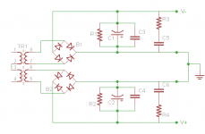
Here is the final schematic of the PSU that I'm using.
TR1 is a Plitron 300VA 18V dual secondaries
B1 and B2 are made with MUR860 diodes
R1 and R2 are 1,500R 2W generic carbon film resistors
C1 and C2 are 15,000uF 50V Panasonic TS-HA capacitors
C3 and C4 are 0.1uF 50V Kemet Golden Max capacitors
R3 and R4 are 1R 0.5W Vishay NFR25 metal film resistors
C5 and C6 are 0.1uF 63V Vishay MKP capacitors
Attachments
As it turns out, this is very much like the chipamp.com snubber PSU design, although I had to use a ceramic cap for the small bypass, as the pin spacing wouldn't allow a polypropylene one. Also, the main caps are a little larger at 15mF as opposed 10mF.
if you believe many of the designer/builders on this Forum then it's your imagination telling you that the High Cap produces more/better bass.Redshift187 said:Different setups:
1. 2,200 uF per rail on rectifier board and 10.1 uF per rail on amp board. Great mid and high range clarity (3 out of 4). Almost no bass below 150 Hz (1 out of 4).
2. 2,200 uF per rail on rectifier board and 1010.1 uF per rail on amp board. Best mid and high range clarity (4 out of 4). Very little bass below 100 Hz (2 out of 4).
3. 15,000 uF per rail snubberized on rectifier board and 10.1 uF per rail on amp board. Decent mid and high range clarity (1 out of 4). Good bass down to around 30 or 40 Hz (3 out of 4).
4. 15,000 uF per rail snubberized on rectifier board and 1010.1 uF per rail on amp board. Good mid and high range clarity (2 out of 4). Excellent bass down to around 20 Hz (4 out of 4).
The difference in bass between the 4,400 and 30,000 uF on the rectifier board was amazing (albeit expected). 30,000 uF has just the right amount of bass in my setup.
"albeit expected" why?
Because it does, but few want to believe us.
But you are confirming Peter Daniel's results that zero rectifier capacitance and high values of decoupling capacitance at the chipamp do give the best midrange.
Seems an excellent case for bi-amplifying all two/three way speakers.
Use the High cap (ver 4) for the bass and the zero cap (ver 2) for the mid and treble. This is NOT an active speaker set up.
for an 8ohm load each half sees a 4om load and the R of RC is 4ohm.
But each amp draws from the alternative rail and this may relax the requirement for the amps to be fed from separate PSUs. If the PSUs were separated then the total capacitance is 160mF (2off @ +-40mF) to get 4Hz @ -1dB into your 8ohm load, (F-3dB=1Hz on PSU when +-40mF drives 4r0).
But the pair drawing alternately on a common PSU may get away with 80mF in total for the same frequency response.
But, I would never bridge a pair of amps that were not designed from the beginning as a bridged (balanced drive) pair.
- Status
- Not open for further replies.
- Home
- Amplifiers
- Chip Amps
- Breaking all the rules, a "custom" bridged story